
100mV Continuity Tester

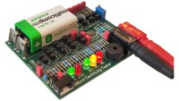
A new take on the classic continuity tester in several ways. This tests with just 100mV across the probes, so it ignores semiconductor junctions and its low input impedance makes it immune to even very large capacitances. It displays continuity to 3 thresholds and generates 3 different tones. All transistor based (instead of 5 op-amps!). Easy to build all-in-one design.
· Test continuity in or out of circuit instantly.
· Only 100mV test voltage across an open circuit.
· 3 low resistance thresholds: 2Ω, 5Ω and 10Ω.
· 3 tones of audible alert.
· Low battery warning.
· Not affected by semiconductor junctions.
· Highly immune to even very large capacitances.
· Fast response (faster than many multimeters).
· Nearly all transistor based (except the regulator).
· Standard 4mm sockets.
Introduction
This design started as a “self challenge”. I wanted to design a good quality continuity tester that would not be fooled by semiconductors and large capacitances. I also wanted to make it with no ICs. Crazy? Yes, of course. The design would be much simpler with a couple of cheap quad Op-Amps, or even a little micro, but where’s the fun in that?
Apart from the voltage regulator (which is a low dropout 5V regulator in a TO92 package), there are no ICs at all in this design.
The design is based around long-tailed-pairs (LTPs). LTPs are most frequently seen at the core of Op-Amps.
One LTP is used as a linear amplifier, to amplify the small voltage across the test probes.
Further LTPs are used as comparators to detect the various thresholds associated with 2Ω, 5Ω and 10Ω being across the test probes.
A final LTP is used for low battery monitoring.
Design Overview
The design comprises of the following stages:
Input Front End - To create 100mV across the probes.
Linear Amplifier - To amplify the voltage across the probes.
Comparators - To switch on LEDs when the amplified voltage reaches certain thresholds.
Oscillator - To produce an audible tone which varies according to the number of LEDs lit.
Comparator - For low battery detection.
Discussie (17 opmerking(en))