

230V AC dimmer, mains isolated, using P12F629
This is a very simple mains isolated dimmer with a triac output (phase control). It uses timer0 to do the timing.
This is a very simple mains isolated dimmer with a triac output (phase control). It uses timer0 to do the timing.
There is no user interface, the value of the triac ignition delay after a zero crossing is defined by setting the reload value of timer0 (Tmr0) in the software directly. This value can e.g. be derived from a user interface or sensor or some algorithm. In the example it is stepped trough a number of values sequentially.
The code is written in mikroPascal from Mikroelektronika, see the code for its details and explanation.
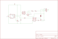
The control part (here a P12F629) is competely isolated from the 230V mains supply:
- the zero crossing detector contains an optocoupler (4N25 or similar),
- the drive of the triac also contains an opto coupler (MOC3025 or similar). Be aware: the latter optocoupler should NOT have a zero cross detection!
The 5V power supply is not drawn in the schematic.
The ignition delay of the triac in series with the load depends on the reload value of Timer0 (Tmr0) in the interrupt routine (zero crossing detected).
The delay (in steps of 64 usecs, the clock of timer0 is 15625 Hz) is given by 256-Tmr0.
The minimum delay (64 us) is achieved by setting the Tmr0 to 255 . This gives maximum power to the load.
The maximum delay needed in this application (10 ms) is achieved by setting Tmr0 to 99 (gives 157 * 64 us = 10.04 ms). This gives no triac ignition at all. Lower values of Tmr0 give the same result.
In the example:
The example uses only these 3 values, see the comments below:
Case Step of
0: Tmr0 := 0; // never ignite triac (delay > 10 ms)
1: Tmr0 := 140; // low value = long delay = late ignition = low power
2: Tmr0 := 175; // average power
3: Tmr0 := 250; // high value = short delay = high power
end;
There is no user interface, the value of the triac ignition delay after a zero crossing is defined by setting the reload value of timer0 (Tmr0) in the software directly. This value can e.g. be derived from a user interface or sensor or some algorithm. In the example it is stepped trough a number of values sequentially.
The code is written in mikroPascal from Mikroelektronika, see the code for its details and explanation.
The control part (here a P12F629) is competely isolated from the 230V mains supply:
- the zero crossing detector contains an optocoupler (4N25 or similar),
- the drive of the triac also contains an opto coupler (MOC3025 or similar). Be aware: the latter optocoupler should NOT have a zero cross detection!
The 5V power supply is not drawn in the schematic.
The ignition delay of the triac in series with the load depends on the reload value of Timer0 (Tmr0) in the interrupt routine (zero crossing detected).
The delay (in steps of 64 usecs, the clock of timer0 is 15625 Hz) is given by 256-Tmr0.
The minimum delay (64 us) is achieved by setting the Tmr0 to 255 . This gives maximum power to the load.
The maximum delay needed in this application (10 ms) is achieved by setting Tmr0 to 99 (gives 157 * 64 us = 10.04 ms). This gives no triac ignition at all. Lower values of Tmr0 give the same result.
In the example:
The example uses only these 3 values, see the comments below:
Case Step of
0: Tmr0 := 0; // never ignite triac (delay > 10 ms)
1: Tmr0 := 140; // low value = long delay = late ignition = low power
2: Tmr0 := 175; // average power
3: Tmr0 := 250; // high value = short delay = high power
end;
Discussie (4 opmerking(en))


geralds 8 jaar geleden
Hi,
this is a fine project but it's not a new project.
The basics comes from the application notes from microchip.
PIC12F508 drives a TRIAC; "PICREF-4".
http://ww1.microchip.com/downloads/en/AppNotes/40171a.pdf
The smallest controller, PIC10F200, drives a TRIAC. (what i built while i played with this small controller)
http://ww1.microchip.com/downloads/en/AppNotes/91094A.pdf
X-10 Home Automation using a PIC16F877A. (this is what i use also in my projects)
http://ww1.microchip.com/downloads/en/AppNotes/00236B.pdf
If you go to the microchip application site you'll find a lot of application tips about this.
Best regards
Gerald
---
Antwoord

DanyR 8 jaar geleden
> i think that's better you don't isolate this on the "hot" side the way to the TRIAC, but that you
> isolate this to the "cold" side to the logic. This is much more easier in handling.
Everything depends on the "width" of the cold side of the logic. In my circuit diagram there is no cold side (ins and outs of the PIC that are not triac related) shown, it has to be added by the user of the circuit. So, in some cases you are right, in others isolating the cold side could be more expensive than only 2 optocouplers...
Antwoord
geralds 8 jaar geleden
Hi,
yes indeed; i know it.
But, i think that's better you don't isolate this on the "hot" side the way to the TRIAC, but that you isolate this to the "cold" side to the logic.
This is much more easier in handling.
You'll need just an opto coupler or LWL for remote controlling the µC.
Gerald
---
yes indeed; i know it.
But, i think that's better you don't isolate this on the "hot" side the way to the TRIAC, but that you isolate this to the "cold" side to the logic.
This is much more easier in handling.
You'll need just an opto coupler or LWL for remote controlling the µC.
Gerald
---
Antwoord
DanyR 8 jaar geleden
> this is a fine project but it's not a new project.
>The basics comes from the application notes from microchip.
None of the microchip documents shows a mains isolated solution. The latter was necessary for me...
The basics of the diagram come from a lot of sources, but I did not know the application notes yet. Thanks for pointing to them!
>The basics comes from the application notes from microchip.
None of the microchip documents shows a mains isolated solution. The latter was necessary for me...
The basics of the diagram come from a lot of sources, but I did not know the application notes yet. Thanks for pointing to them!
Antwoord
Toon meer
3 Opmerking(en)

magicChristian 8 jaar geleden
one point I do not understand is why you need an isolation if you have no element to be touched.
As an addition I would use the remainig GPIO´s to change the duty rate, one Button to step up, one to step down and a third to write the duty value into EEPROM.
Or if you use a PIC with ADC you could use a Poti to set the duty p.E. PIC16F18313
You could save the 4 Diodes from Bridge rectifier if you use an Optocoupler with bidirectional input.
my Email address is: christian.jorde@gmx.at
Antwoord
DanyR 8 jaar geleden
Hi Christian, This is the problem: the voltage across the zener diode is probably expected to be almost always 6.8V, except at the zero crossings, where it is supposed to be zero volts for a short time.
If you look at the "Simulation over longer time" a few posts back, then you can see that, after a while, the voltage across the zener is always 6.8V, and has no longer zero crossing pulses. This is probably due to C1 building up a charge and never uncharge.
The current state of the project (it is actually only a part of a project, it does not actually do anything on its own) is an extra emitter follower at the "cold" side of the optocoupler and a resistor of a much higher value at the "hot" side (with very low dissipation).
I will publish the updated circuit diagram soon.
Antwoord
magicChristian 8 jaar geleden
Hello Dany,
when I came home I wanted to know what is wrong with my circuit suggestion:
The voltage after the bridge rectifier i thought it will be most of the time at 6.8 V and have short phase to got to approx. to zero V. But this is not the case and therfor the C2 will never be discharged.what is your last status on this project?
Antwoord
geralds 8 jaar geleden
Hi Christian,
the PIC16F18313 is a fine new controller, but i suggest that using a controller that have included a ZCD would be a little bit better.
http://www.microchip.com/search/searchapp/searchparts.aspx?q=zcd&resperpage=10&id=3
Best regards
Gerald
---
the PIC16F18313 is a fine new controller, but i suggest that using a controller that have included a ZCD would be a little bit better.
http://www.microchip.com/search/searchapp/searchparts.aspx?q=zcd&resperpage=10&id=3
Best regards
Gerald
---
Antwoord
DanyR 8 jaar geleden
> Hi Dany, the simulation of my circuit looks not correct to me. It should have only a short pulse activating the octocoupler.
I can not find the difference between the simulation and your circuit diagram. In the simulation I used first 2.2uF as C1, but the result is the same as with 1 uF.
Attached both circuit diagrams. Could you check the simulation one please? Thanks.
I re-simulated your circuit with C1 varying from 0.1uF to 2.2 uF and to my surprise I saw that the circuit did not work any longer after a while, depending on the value of C1 (for 2.2uF the circuit gave up after 0.85 seconds, lower capacities gave up earlier).
I think the reason for this is that C1 gete fully loaded and supplies no base current to the transistor any more... See attachtment.
Antwoord
magicChristian 8 jaar geleden
Hi Dany, the simulation of my circuit looks not correct to me. It should have only a short pulse activating the octocoupler.
It is a good idea to use a OC with high CTR and this needs low current at input. But you can calculate the delay from zero crossing: currrent needed for switching multiplied by R1 added 2 Diode voltages.
I am in Italy near Ancona the next 14 days.
Regards Christian
It is a good idea to use a OC with high CTR and this needs low current at input. But you can calculate the delay from zero crossing: currrent needed for switching multiplied by R1 added 2 Diode voltages.
I am in Italy near Ancona the next 14 days.
Regards Christian
Antwoord
DanyR 8 jaar geleden
Hi Christian, I think the best solution is take an optocoupler with a high CTR (e.g. a darlington optocoupler) , or make it high by adding one axtra emitter follower at the output.
Added a circuit diagram with an extra emitter follower. The series resistor to the mains is 2.2Meg here, which dissipates 25mW average. The output pulse are very sharp, nicely around zero crossing.
Added a circuit diagram with an extra emitter follower. The series resistor to the mains is 2.2Meg here, which dissipates 25mW average. The output pulse are very sharp, nicely around zero crossing.
Antwoord
DanyR 8 jaar geleden
Hi Christain, I tested your proposal. It works, but still the series element to the mains is a resistor (in this case 180K) to feed the optocoupler are the added electronic circuit.
So I wondered why I needed 44K (with more dissipation) in my first circuit. The answer is in the value of the resistor at the output side of the optocoupler. If I change that one also in 47K (in stead of 10K) then the "simple" resistor curcuit also gives good results with an 180K resistor (and a dissipation of 300 mW average). See both LTSpice simulations below.
So I wondered why I needed 44K (with more dissipation) in my first circuit. The answer is in the value of the resistor at the output side of the optocoupler. If I change that one also in 47K (in stead of 10K) then the "simple" resistor curcuit also gives good results with an 180K resistor (and a dissipation of 300 mW average). See both LTSpice simulations below.
Antwoord
magicChristian 8 jaar geleden
Hello Dany, I was 2 days out of town and attached you find my suggestion of a good trigger circuit.
One goal is to have lowest dissipation and the other to come close to zero crossing.
First is achieved to have short trigger pulse but we need a capacitor to provide the energy around zero crossing. Second is a kind amplifier with a transistor to switch soon when mains is rising. I would appriciate if you can simulate this circuit - maybe with a variety of C1.
Antwoord
DanyR 8 jaar geleden
Hi Christian,
I did saw some flicker caused by difference in triac ignition moment between positive and negative alternance, but I must admit the circuit was in a primitive testing state then. I do not know which difference will become actually visible as flickering. During that test I was using an ordinary incandescant bulb of 40W/230V.
Aftewards I changed the circuit to the one with the bridge rectifier to make sure it was absolutely symmetrical.
> I thought a while about a more precise isolated Zero crossing detection. And I have one but it needs 7 components at the mains side (2 add. diode, 1 Zener, 2 Cap 1 R and 1 TUN)
And it will have about 1/5 of dissipation. The trigger point is around 3 V of rising mains - 2 V are caused by the bridge rectifier. If you are interested I will put it in a mailable form.
Yes I am very interested in the circuit.
In the mean time I did some LTSpice simulation, see attachment.
Antwoord
magicChristian 8 jaar geleden
Hi Dany
Thanks, I do like your Spice simulation.
I would bet one cannot see any flicker if the duty is not exact equal every half period.
What kind of lamp you want to use?
I thought a while about a more precise isolated Zero crossing detection. And I have one but it needs 7 components at the mains side (2 add. diode, 1 Zener, 2 Cap 1 R and 1 TUN)
And it will have about 1/5 of dissipation. The trigger point is around 3 V of rising mains - 2 V are caused by the bridge rectifier. If you are interested I will put it in a mailable form.
Regards from Graz to Nieuwport
Christian
Antwoord
DanyR 8 jaar geleden
Hi Christian,
a CTR of the zero crossing optocoupler of 20% is indeed unacceptable, see the LTSpice simulation (blue curce = 100%, red=50% and green is 20%). I was a little bit mislead by the 4N25 spice model, its CTR there is 74%, see http://www.edaboard.com/thread345500.html.
From 50% onwards seems to be acceptable, so the TIL111 should be ok.
Antwoord
DanyR 8 jaar geleden
Hi Cristian, thanks for your valuble comments.
> the PIC16F18313 is one of the last devices and has a lot more features and is cheaper.
I suppose thet there are indeed cheaper and more powerfull pics, but the 12F629 happened to be present in my drawer. :-)
> Two examples of AC input optocouplers : MOC256 from Fairchild or VOS628A-3 from Vishay. The CTR is not exactly the same in both directions, which means the trigger for pos and neg Halfwave could be some µs different based on zero crossing.
The difference between the CTR in both directions can cause flicker of e.g. the lamp driven by the triac. This visible effect can be annoying in this case, but is not for other loads (e.g. heater).
> Your circuit with 4N25 will produce a delay depending on CTR. With minimum CTR of 20 % it will switch when Voltage raised to 55 V . The delay from zero crossing is 550 or 460 µs
Yes, I am aware of that. This can be unwanted in certain applications. I built actually my prototype with the TIL111, but i did not know if that one could be easily obtained from the shop. The min CTR of the TIL111 is 50, so this gives a better result.
> To avoid the relativly high dissipation in R2 and R3 one can use a capacitor instead. This shifts the trigger impulse, but the µC can use a timer to shift it back. The internal clock is better than 1% correct at 25°C. And it can be calibrated automatically by using the Period of mains (20 or 16,67 ms).
Nice idea. I will study it. Thanks.
> Where are you located because you use 230 Vac?
Belgium. :-)
Thanks and kind regards,
Dany
Antwoord
magicChristian 8 jaar geleden
Hi Dany,
the PIC16F18313 is one of the last devices and has a lot more features and is cheaper.
Two examples of AC input optocouplers : MOC256 from Fairchild or VOS628A-3 from Vishay.
The CTR is not exactly the same in both directions, which means the trigger for pos and neg Halfwave could be some µs different based on zero crossing.
Your circuit with 4N25 will produce a delay depending on CTR. With minimum CTR of 20 % it will switch when Voltage raised to 55 V . The delay from zero crossing is 550 or 460 µs
To avoid the relativly high dissipation in R2 and R3 one can use a capacitor instead. This shifts the trigger impulse, but the µC can use a timer to shift it back. The internal clock is better than 1% correct at 25°C. And it can be calibrated automatically by using the Period of mains (20 or 16,67 ms).
Where are you located because you use 230 Vac?
Christian
Antwoord
DanyR 8 jaar geleden
Thanks for the feedback!
> I do not understand is why you need an isolation if you have no element to be touched.
You are right.The circuit has of course to be extended with some kind of user interface or machine interface to be able to control the triac ignition delay. Adding those kind of things makes an isolation necessary. The isolation has been added to make this extension possible.
>As an addition I would use the remainig GPIO´s to change the duty rate, one Button to step up, one to step down and a third to write the duty value into EEPROM.
>Or if you use a PIC with ADC you could use a Poti to set the duty p.E. PIC16F18313
Indeed, these are examples of a possible user interface.
The circuit as presented in the project is a native one, without interface to change the triac ignition moment.
> You could save the 4 Diodes from Bridge rectifier if you use an Optocoupler with bidirectional input.
Indeed. Thanks for the suggestion. One of the attention points is here that the circuit must behave exactly the same for both positive and negative period half of the mains. I do not know if this is the case with bidirectional input optocouplers.
Antwoord
Toon meer
20 Opmerking(en)
Updates van de auteur
DanyR 7 jaar geleden
It is simply a potmeter (R6 in the circuit diagram), connected to an analog input of the PIC, that will control the dimmer. I had to change the PIC to the PIC12F675 to have an analog input.
Of course this is one of the most simple user controls that are possible.
The potmeter can e.g. be replaced by an RC filter, making it possible to steer the dimmer with a PWM signal (the filter has to convert this to a DC voltage, the required input of the analog input).
Source code of the Dimmer with User control (23kb)