

2.4 GHz wireless digital headphone (Texas Purepath)
The project is based on the Texas CC8520 Purepath Technology through the A8520E24A91 ANAREN module which integrates a CC8520 and a RF amplifier CC2591.
The project is based on the Texas CC8520 Purepath Technology through the A8520E24A91 ANAREN module which integrates a CC8520 and a RF amplifier CC2591.
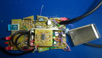
The receiver (PS), although an ANAREN module is a transceiver, operates in the "hosted mode" to allow future functionality, thanks to the data channel, like remote control from the transmitter, channel selection, ... It's powered with a USB power bank.
The PIC 18F2550 (bottom side) acts also as a USB loader (as the Texas CC Debugger) to prgram the ANAREN with the *.hex generated by the Texas "Configurator" software.
See the synoptic PDF.
The sound quality is (very) good. In free field and with the transmitter in height, 75 m are achieved. The audio flux is PCM 16. To enhance the strength of the wireless audio link, an almost inaudible SLAC compression can be activated on the transmitter side, the receiver will follow.
An adjustable limiter can avoid to hurt the ears.
MUSE capacitors are used on the audio path.
In spite of efforts (especially galvanic isolation between the digital and the analog circuitry - see synoptic), a small noise of digital origin can be hear. Please, help! More copper on my PCB ? Ferrite bead ?
When the stereo signal is taken just after the CNA (CS4334, bottom side) to be sent to an HIFI amplifier, the noise becomes negligible.
Instead of a wireless headphone application, this electronic architecture can be used for sound reinforcement. The latency is 20 ms max.
The transmitter (PM) side is on a "Protoboard". The CAN is a WOLFSON WM8783. The .HEX was loading in the ANAREN thanks to a PIC18 and a FTDI USB serial cable.
The PCB of the receiver is formatted to accommodate in a low cost HAMMOND 1553C box.
Discussie (2 opmerking(en))
ClemensValens 10 jaar geleden
Hello Zoup,
So, how are things going? Is your system operational? Please let us know.
Regards,
Clemens
ClemensValens 10 jaar geleden
Bonjour zoup,
Noise can enter your circuit in several ways:
Galvanic isolation will separate the power supplies and ground connections but how are your power supplies powered? Noise can travel up & down the mains lines so if both power supplies are connected to the same mains then your galvanic isolation may not help you much. To avoid interference entering through cables you would place ferrites in series with _every_ wire that leaves the PCB or box. See if things get better when you use batteries.
Your drawings and photos are not clear enough to be very helpful. I count two microcontrollers, one on each side of the galvanic barrier. Can you test your circuit without them? With only one? Maybe it is U5 that causes the problems? If so, then your galvanic barrier is pretty useless.
Shielding is good against radiation, but maybe the noise is produced inside the shield? You have lots of digital (controlled) parts in your analog circuit. Chips can radiate, PCB traces too. Capacitors can pick up noise, PCB traces can too.
Ground planes often help, but you don't seem to have any. How do currents flow? Do you have one long supply/ground line powering all parts or do they have branches? How are they connected? Can digital and analog currents mix? Decoupling? Crosstalk? Clock lines? Any other high-speed signals running around?
You should post complete PCB layouts and full schematics if you want help beyond guessing.
Regards,
Clemens