

6-digit VFD Clock with ESP32
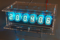
The 6-digit VFD clock is built around 6 Russian IV-22 VFD tubes and looks very familiar to the popular 6-digit Nixie Clock.
The 6-digit VFD Clock design was inspired by the very popular 6-digit Nixie Clock. We opted to use IV-22 VFD tubes for the digits together with DM160/CV6094 tubes for the colon separators. Both types of tubes are still available in relatively large quantities. As the IV-22 VFD tubes have the same dimensions as the IN-12 nixie tubes used in the original clock, we decided to use the same setup and dimensions for the new design. With a similar acrylic enclosure the clock looks very familiar, yet different.
The heart of the clock consists of an ESP-32-DevKitC module from Espressif. Time is synchronized via NTP over a WIFI connection with the internet. The settings of the clock can be altered via USB or via the WIFI network connection.
The VFD tubes are driven in a 2 x 3 multiplex mode using a Microchip HV518P high voltage shift register driver. A simple 7555 based step-up converter generates the 50 V anode voltage, while a Texas Instruments PTH08080W step down module supplies the 1.1 V filament voltage.
Features:
- 9V DC power supply, 3 W maximum power consumption
- 12 or 24 hour time format
- date format dd/mm/yyy, mm/dd/yyyy or yyyy/mm/dd
- temperature display in Celsius or Fahrenheit
- supports DS18B20, DS18S20, DS1822, LM75 and SE95 temperature sensors
- RGB tube backlighting with selectable color options
- different colon separator modes (flashing, AM/PM, ...)
- 1-wire and I2C interface
- sleep mode with adjustable night light option and wake-up via a push button
- fully designed for through hole components and modules
- command server for network configuration
- the clock firmware was written using the Arduino environment
Discussie (37 opmerking(en))

H M Hesky 3 weken geleden
Dear Alan, we are facing problems in programming the ESP it is a pity that we cannot use the beautiful clock kit.
Do you see a possibility to buy a preprogrammed ESP from you - either a complete programmed new board or sending you the original ESP and you are returning it in a programmed condition. Keep in mind that I am willing to pay for that special "service". Thank you in advance for your help Met vriendelijke Groet Michael
Do you see a possibility to buy a preprogrammed ESP from you - either a complete programmed new board or sending you the original ESP and you are returning it in a programmed condition. Keep in mind that I am willing to pay for that special "service". Thank you in advance for your help Met vriendelijke Groet Michael
Antwoord
Toon meer
0 Opmerking(en)

DE0090138ID 1 jaar geleden
Hallo,
ich hatte den Bausatz zu der VFD-Uhr seit längerer Zeit herumliegen, bin aber erst diese Woche dazugekommen, mich an die Inbetriebnahme (konkret Software laden) zu machen.
Dabei scheitere ich an folgendem Problem:
Nach der Programmierung und Eingabe der diversen Daten in den ESP 32 leuchtet zwar die LED-Beleuchtung in verschiedenen Farben, jedoch bekomme ich scheinbar keine Verbindung zum Netzwerk (WLAN funktioniert und SSID sowie Passwort habe ich mehrfach überprüft, ich hatte auch ein zweites Netzwerk probiert, selbes Problem)
Jedenfalls zeigt die Uhr nur "-- -- --".
Kann mir hier bitte jemand weiterhelfen? Mit den bisher hier genannten Hinweisen komme ich leider nicht weiter...
Danke und Gruß
Peter
Antwoord
Toon meer
0 Opmerking(en)


Henri Kummer 4 jaar geleden
Hallo,
ich habe erst jetzt meine Uhr aufgebaut. Sie zeigt aber nichts an. Ich habe nochmal alles überprüft.
Können Sie mir bitte helfen?
ets Jun 8 2016 00:22:57
rst:0x1 (POWERON_RESET),boot:0x13 (SPI_FAST_FLASH_BOOT)
flash read err, 1000
ets_main.c 371
ets Jun 8 2016 00:22:57
rst:0x10 (RTCWDT_RTC_RESET),boot:0x13 (SPI_FAST_FLASH_BOOT)
configsip: 0, SPIWP:0xee
clk_drv:0x00,q_drv:0x00,d_drv:0x00,cs0_drv:0x00,hd_drv:0x00,wp_drv:0x00
mode:DIO, clock div:1
load:0x3fff0018,len:4
load:0x3fff001c,len:1216
ho 0 tail 12 room 4
load:0x40078000,len:9720
ho 0 tail 12 room 4
load:0x40080400,len:6352
entry 0x400806b8
WiFi event 0 - SYSTEM_EVENT_WIFI_READY
WiFi status 255 - NO SHIELD
WiFi event 2 - SYSTEM_EVENT_STA_START
WiFi status 6 - DISCONNECTED
wifi_exec_state 0->1
WiFi event 5 - SYSTEM_EVENT_STA_DISCONNECTED
WiFi status 4 - CONNECTION FAILED
WiFi lost connection
wifi_exec_state 1->3
wifi_exec_state 3->0
wifi_exec_state 0->1
WiFi event 4 - SYSTEM_EVENT_STA_CONNECTED
WiFi status 0 - IDLE
WiFi connected
WiFi event 7 - SYSTEM_EVENT_STA_GOT_IP
WiFi status 3 - CONNECTED
WiFi got IP: 192.168.178.91
wifi_exec_state 1->2
NTP_Start
ntp_exec_state 0->1
ntp_exec_state 1->2
ntp_exec_state 2->3
ntp_exec_state 3->4
NTP query: packet received 48 bytes
* time_t: 1610295845
* UTC: 2021-01-10 16:24:05
ntp_exec_state 4->0
s d
WIFI:
* SSID: Werkstatt-PC
* Local: 192.168.178.91
* Subnet: 255.255.255.0
* Gateway: 192.168.178.1
* DNS 1: 8.8.8.8
* DNS 2: 0.0.0.0
* Method: dynamic
* Hostname: VFD-CLOCK
Serial:
* Echo commands: yes
Command server:
* Echo commands: no
NTP:
* Hostname: pool.ntp.org
* Address: 0.0.0.0
* Method: look up hostname
OWTemp:
* Enabled: yes
LM75/SE95D:
* Enabled: no
* ADSEL: 0
Clock:
* Active adjustment: 1
* Adjust 1: +01:00:00
* Adjust 2: +02:00:00
* Adjust 3: +01:00:00
* Adjust 4: +02:00:00
* Show date: yes
* Date format: DD-MM-YY
* Date separators: always off
* Hour format: 24
* Hour leading zero: yes
* Time separators: blinking
* Show temperature: yes
* Temperature format: Celsius
RGB:
* Method: gradient
* Solid RGB: 4095 0000 4095
* Gradient: RED +2200 +0048 0086 0171
* GREEN +4930 -0048 0142 0171
* BLUE -0530 -0048 0028 0171
* Sleep RGB: 0000 0000 0000
Main:
* WIFI connect: yes
* NTP request: yes
* NTP refresh rate: 01:00:00
* Command server: yes
* Sleep time: 23:00:00
* Wakeup time: 06:30:00
* Sleep mode: yes
OK
Vielen Dank
Henri
Hallo,
ich habe den Fehler doch noch gefunden. Nach entfernen von T3, ging die Anzeige auf einmal. Ich habe gleich ein paar davon bestellt.
Viele Grüße
Henri
Antwoord
Toon meer
0 Opmerking(en)


Roy Noordhuizen 4 jaar geleden
Hi is this set still for sale? I can not find it in the shop so was wondering if you might have a list of compononts or even a spare set left :-)
Antwoord

Alan Knight 4 jaar geleden
Hi Roy,
Sorry have not got a spare set, but have attached a list of components as requested.
Stay safe.
Alan
Sorry have not got a spare set, but have attached a list of components as requested.
Stay safe.
Alan
Antwoord

Marvin Hollander 4 jaar geleden
Roy,
I came across 100 IV-22's on ebay. I'm currently gathering all the components to make 17 complete sets for this clock, including PCB's. But still waiting for components from the USA. I will let you know. I am not affiliated with Elektor or the designer. But I thought this is such a cool project I wanted more of these.
I came across 100 IV-22's on ebay. I'm currently gathering all the components to make 17 complete sets for this clock, including PCB's. But still waiting for components from the USA. I will let you know. I am not affiliated with Elektor or the designer. But I thought this is such a cool project I wanted more of these.
Antwoord
Roy Noordhuizen 4 jaar geleden
Hi Marvin,
Same goes for me except instead of buying 100, I got my hands on 6 of 'em.
I would be very much interested in getting one of those sets. It would be cool if you could reach out to me via r.noordhuizen at gmail dot com so that you can maybe me get me a price.
Thanks in advance and hope hearing from you soon.
Antwoord

Toon meer
1 Opmerking(en)
Alan Knight 4 jaar geleden
Hi,
I have looked at the information you have sent me, but many links appear
to be broken.
I cannot find what android app I need to download to my phone to connect
to this project (app was shown in video, but no name given).
Thanks for your help.
Stay safe.
Alan Knight
I have looked at the information you have sent me, but many links appear
to be broken.
I cannot find what android app I need to download to my phone to connect
to this project (app was shown in video, but no name given).
Thanks for your help.
Stay safe.
Alan Knight
Antwoord
Toon meer
0 Opmerking(en)

Jochen 5 jaar geleden
Hallo,
clock is connected with WIFI, but clock doesn`t work (only g-segments are lighting, - - - - - - )
puTTY shows (again and again):
DNS_Host_By_Name_CB: pool.ntp.org -> no IP address
NTP_Start
DNS_Host_By_Name_Init: err -5, pending
Elektor page shows a (new) link to: https://www.ntppool.org/de/use.html
Question: are following lines from your manual still okay? :
ntp set hostname "pool.ntp.org"
ntp set addr 0.0.0.0
ntp set method hostname
Please could you help?
Vielen Dank!
Jochen
Antwoord
Jochen 4 jaar geleden
Hi Ilse,
the clock works!
These are my final settings:
wifi set ssid "FRITZ!Box 7490"
wifi set password "xxx..."
wifi set local 192.168.178.123
wifi set subnet 255.255.255.0
wifi set gateway 192.168.178.150
wifi set dns 1 192.168.178.150
wifi set dns 2 0.0.0.0
wifi set method dynamic
serial set echocmd yes
cs set echocmd no
ntp set hostname "pool.ntp.org"
ntp set addr 0.0.0.0
ntp set method hostname
.....
Thanks a lot for your great help,
and thanks to Claude, too
Stay healthy!
Jochen
Antwoord

Axiris 5 jaar geleden
Hi Jochen,
According to your settings, your local IP address is 192.168.178.123 with subnet mask 255.255.255.0 while your gateway and dns 1 address is 192.168.1.254
This means that your clock never can communicate with the gateway and the dns server.
Your local IP address should be something like 192.168.1.xxx, for example 192.168.1.123
Please note that IP addresses should be unique within your network. If your clock has 192.168.1.123, no other device should use that IP address.
Kind regards,
Ilse
Antwoord
Jochen 5 jaar geleden
Hi Ilse,
please would you see here:
wifi set ssid "FRITZ!Box 7490"
wifi set password "xxx..."
wifi set local 192.168.178.123
wifi set subnet 255.255.255.0
wifi set gateway 192.168.1.254
wifi set dns 1 192.168.1.254
wifi set dns 2 0.0.0.0
wifi set method static
serial set echocmd yes
cs set echocmd no
ntp set hostname "pool.ntp.org"
ntp set addr 0.0.0.0
ntp set method hostname
owtemp set enabled yes
lm75 set enabled no
lm75 set adsel 0
clock set adjust + 01 00 00
clock set showdate yes
clock set dateformat dmy
clock set datesepmode off
clock set hourformat 24
clock set hourlz yes
clock set timesepmode blink
clock set showtemp yes
clock set tempformat celsius
rgb set grad id 1
rgb set solid id 17
rgb set sleep raw 0 0 0
rgb set method grad
rgb set grad apply
main set wificonnect yes
main set ntprequest yes
main set ntprefresh 01 00 00
main set cmdsrvstart yes
main set sleeptime 01 00 00
main set wakeuptime 06 30 00
main set sleepmode yes
settings write
B.R.
Jochen
Antwoord

Claude Millasson 5 jaar geleden
Hello
for me with the last software ( june 2019 ) with 2 time sommer and winter
It's s work fine
(xxxx is my personal information....)
BR
Claude
*************************************************
wifi set ssid "xxxxxxxxx"
wifi set password "xxxxxxxxxxxxxxxx"
wifi set local 192.168.1.55
wifi set subnet 255.255.255.0
wifi set gateway 192.168.1.1
wifi set dns 1 195.186.1.162
wifi set dns 2 195.186.4.162
wifi set method dynamic
wifi set hostname “VFD-CLOCK”
serial set echocmd yes
cs set echocmd no
ntp set hostname "pool.ntp.org"
ntp set addr 0.0.0.0
ntp set method hostname
owtemp set enabled yes
lm75 set enabled no
lm75 set adsel 0
clock set adjust 1 + 01 00 00
clock set adjust 2 + 02 00 00
clock set adjust 3 + 01 00 00
clock set adjust 4 + 02 00 00
clock set showdate yes
clock set dateformat dmy
clock set datesepmode off
clock set hourformat 24
clock set hourlz yes
clock set timesepmode blink
clock set showtemp yes
clock set tempformat celsius
rgb set grad id 1
rgb set solid id 17
rgb set sleep raw 0 0 0
rgb set method grad
rgb set grad apply
main set wificonnect yes
main set ntprequest yes
main set ntprefresh 01 00 00
main set cmdsrvstart yes
main set sleeptime 23 00 00
main set wakeuptime 06 30 00
main set sleepmode yes
settings write
*****************************************
Antwoord
Toon meer
6 Opmerking(en)

Felix Härtl 5 jaar geleden
Hallo ich stehe vor einem Problem,
Ich bin momentan bei dem Schritt die Komandos zum einrichten der Uhr über PuTTY hochzuladen.
Das hier sind die Komandos die ich ins PuTTY eingebe:
wifi set ssid "FRITZ!Box 7590 AL"
wifi set password "******"
wifi set local 192.168.178.25
wifi set subnet 255.255.255.0
wifi set gateway 192.168.178.1
wifi set dns 1 192.168.178.1
wifi set dns 2 0.0.0.0
wifi set method static
serial set echocmd yes
cs set echocmd no
ntp set hostname "pool.ntp.org"
ntp set addr 0.0.0.0
ntp set method hostname
owtemp set enabled yes
lm75 set enabled no
lm75 set adsel 0
clock set adjust + 01 00 00
clock set showdate yes
clock set dateformat dmy
clock set datesepmode off
clock set hourformat 24
clock set hourlz yes
clock set timesepmode blink
clock set showtemp yes
clock set tempformat celsius
rgb set grad id 1
rgb set solid id 17
rgb set sleep raw 0 0 0
rgb set method grad
rgb set grad apply
main set wificonnect yes
main set ntprequest yes
main set ntprefresh 01 00 00
main set cmdsrvstart yes
main set sleeptime 01 00 00
main set wakeuptime 06 30 00
main set sleepmode yes
settings write
Es haakt wohl am NTP Server. Im PuTTY wird dauerhaft folgender Schritt wiederholt:
NTP_Start
DNS_Host_By_Name_Init: err -5, pending
DNS_Host_By_Name_CB: pool.ntp.org -> no IP address
Im Manual zu der Uhr sieht man auf Seite 22 den Code:
NTP_Start
DNS_Host_By_Name_Init: err -5, pending
DNS_Host_By_Name_CB: pool.ntp.org -> IP adress 158.43.128.33
NTP_query: packet recieved 48 bytes
Scheinbar findet er bei mir die IP nicht oder kann nicht darauf zugreifen.
Oder muss ich in den Komandos noch etwas abändern?
Hat jemand eine Ahnung wie man hier vorgeht?
Vielen Dank im Voraus
Grüße Felix
Antwoord
Toon meer
1 Opmerking(en)

D.J.M. Leijendeckers 5 jaar geleden
Beste,
Ik heb de software eindelijk in de esp32,
maar nu is mijn vraag waar ik het configuratie bestand kan vinden om de klok te kunnen instellen.
vriendelijke groet D.L.
Ik heb de software eindelijk in de esp32,
maar nu is mijn vraag waar ik het configuratie bestand kan vinden om de klok te kunnen instellen.
vriendelijke groet D.L.
Antwoord
Axiris 5 jaar geleden
Het configuratiebestand en de uitleg staan in de handleiding vanaf bladzijde 27 en verder.
https://www.axiris.eu/download/VFD_Clock_Assembly_Manual_rev_4.pdf
Je kan gewoon de tekst uit de handleiding kopiëren en in een leeg tekstbestand plakken.
The configuration file and an explanation on how to use it are in the manual from page 27 and on.
https://www.axiris.eu/download/VFD_Clock_Assembly_Manual_rev_4.pdf
You can copy the text from the manual and paste it into an empty text file.
Vriendelijke groet,
Kind Regards,
Ilse
https://www.axiris.eu/download/VFD_Clock_Assembly_Manual_rev_4.pdf
Je kan gewoon de tekst uit de handleiding kopiëren en in een leeg tekstbestand plakken.
The configuration file and an explanation on how to use it are in the manual from page 27 and on.
https://www.axiris.eu/download/VFD_Clock_Assembly_Manual_rev_4.pdf
You can copy the text from the manual and paste it into an empty text file.
Vriendelijke groet,
Kind Regards,
Ilse
Antwoord
Toon meer
2 Opmerking(en)

DON W 5 jaar geleden
I have been having a problem that has just started over the last few months, I don't recall seeing the issue when I first built my clock about a year ago.
Intermittently, typically, 3 days out of every 4, or, worse, when sleep time ends, the clock does not wake up. I'll see a flashing display, single segments on each tube. The only way to bring it back to life is to connect the esp32 to my computer via usb, which i assume does some sort of soft reset on the esp32. So far, connecting the esp32 to my computer via usb is the only solution.
Even stranger, in the midst of troubleshooting, I have changed the sleep and wake times to try to witness exactly what is happening when the clock tries to wake up, but am not able to duplicate the issue. The clock goes to sleep and wakes up fine, which has me thinking this is more an intermittent hardware issue, as opposed to a software issue or setting conflict.
I have tried and changed multiple settings, one at a time, so far none of them have resolved the issue. I've upgraded to the latest firmware, thinking that would help just by reloading the software, no luck.
It seems something is not happening within the ESP32 at the point of wakeup, but I'm at a loss of how to figure out what is going on..or..if I might simply have a flaky ESP32.
Any suggestions?
Antwoord
DON W 5 jaar geleden
That certainly does make sense. And this was a regulated supply, even though the clock itself has its own internal regulated power system. I've never seen one quite so unstable, to where my DVM was in constant change..I didn't bother to scope the output, but I can imagine how it would look.
So far, with a new supply, no further issues.
So far, with a new supply, no further issues.
Antwoord
Axiris 5 jaar geleden
We've seen power supplies that can't cope well with a (substantial) change in load. E.g. when the device draws more current, the output voltage of the PS drops, and as a result the device draws even more power, etc. until the device powers down. Since the PS is still active it then could produce its normal voltage output, and the device may power up again. In some cases, a periodic power-cycling occurs. From the device's point of view, it's like plugging out and plugging in the PS at a constant pace.
When the clock goes into sleep mode, it draws considerably less power as the VFD tubes are turned off. When the clock awakens, the clock fires up the VFD tubes and the load on the PS goes up. At this point the issue may occur.
Good luck!
When the clock goes into sleep mode, it draws considerably less power as the VFD tubes are turned off. When the clock awakens, the clock fires up the VFD tubes and the load on the PS goes up. At this point the issue may occur.
Good luck!
Antwoord
DON W 5 jaar geleden
And the plot thickens..
After giving the board a once over and heating up a few connections that didn't look bad/cold, but, just were not as "clean" as I'd like them to be, I decided to take another look, as had been suggested, at the power issue. I didn't see anything on the board that would suggest this issue was a cold solder joint that was intermittent or in some way causing a problem.
I'm pretty sure I had verified my adapter was supplying a steady solid 9 VDC, but, much to my surprise (among other reactions), I was seeing the output drifting from as low as 7.2 V up to about 8.8...never reaching 9, and definitely not the stability of a regulated power adapter. Those reading were just with my DVM monitoring, so who knows how much this thing could have been varying under any kind of load. And as erratic as it behaved, makes me wonder if it was fluctuating enough to cause the ESP32 to behave erratically. If this is the root cause, the question of why it only happened in sleep mode, I have no idea, but I'll trade not understanding what exactly triggered the issue for a stable clock.
I dug up another 9VDC/500 ma supply from my drawer full of power supplies, its running on that one now, we'll see how it behaves over the next week or so.
Antwoord
DON W 5 jaar geleden
Well, since Saturday, with the new ESP32 module installed, the clock was rock solid; the issue had not reoccured.
This morning, I was in my office, and I have a flashing dispay...the problem is back.
The fact it ran fine for days (at least 7 sleep/wake cycles after replacement) has me really scratching my head.
Going to give the board a good once over and make sure I don't have a cold solder joint I'm not missing, to where the replacment of the ESP32 flexed the board enough to where it chased the issue away temporarily. A long shot, I know, but easy to eliminate.
I can also run it off of my bench supply to eliminate it being a power supply issue. I still see that as unlikely, but its one more thing easily eliminated.
Antwoord
DON W 5 jaar geleden
Here are current settings. I still need to spend some time to sort out the new software features that allows me to switch create profiles for daylight and non-daylight savings time, but its just as easy for me to just log in and change to offset, so, its low priority.
Here is the file I created during initial build, and loaded yesterday. Let me know if you see anything that concerns you.
wifi set ssid "HomeNetwork_downstairs_2.4"
wifi set password "XXX"
wifi set local 192.168.0.140
wifi set subnet 255.255.255.0
wifi set gateway 192.168.0.1
wifi set dns 1 192.168.0.1
wifi set dns 2 8.8.8.8
#wifi set method dynamic
wifi set method static
ntp set hostname "pool.ntp.org"
ntp set addr 0.0.0.0
ntp set method hostname
#ntp set method addr
owtemp set enabled no
lm75 set enabled no
lm75 set adsel 0
clock set adjust -04 00 00
clock set showdate yes
clock set dateformat mdy
clock set datesepmode off
clock set hourformat 12
clock set hourlz yes
clock set timesepmode blink
clock set showtemp yes
clock set tempformat celsius
rgb set grad id 1
rgb set solid id 17
rgb set sleep raw 0 0 0
rgb set method grad
rgb set grad apply
main set wificonnect yes
main set ntprequest yes
main set ntprefresh 00 05 00
main set cmdsrvstart yes
main set sleeptime 23 30 00
main set wakeuptime 05 00 00
main set sleepmode yes
settings write
Antwoord
DON W 5 jaar geleden
Regarding the power supply, I don't recall that one was included, but if there was, thats the one I'm using. Its a regulated supply, 9V/2A. That said, I do have some recollection of having to purchase a supply, as I didn't have any 9V supplies in my parts stock. And my PS does not have an LED on it, though, in the midst of troubleshooting the issue, i verifed the PS output was stable and not fluctuating.
Yesterday I went ahead and swapped out the ESP32. After reloading everything, I put the clock into sleep mode for 12 hours, and it was fine; the issue did not occur. I then reset it for its normal sleep/wake time cycle, and it was stable, issue did not occur. So thats approximately 18 hours of sleep time out of the last 24 without the issue occuring. I see that as a very good indication that the issue is resolved.
I want to see it run without issues for a few more days, but at this point it does appear the ESP32 is the culprit. I don't know the architecture of the ESP32 to the level of where I can make an educated guess as to the root cause, but definitely am curious as to what could have been happening.
I'll update again in a few days, or sooner if the problem reoccurs.
Antwoord
Axiris 5 jaar geleden
Thanks for the clear and elaborate replies.
You're right, the command is "clock suspend". It activates sleep mode the same way as the timed sleep mode. Note that sleep mode means that software stops driving the VFD tubes and puts the backlight LEDs in a fixed color scheme as specified by command "rgb set sleep". The esp32 keeps executing the software.
I'm starting to think something goes wrong at the level of the power supply. I'm now assuming you're using the included power supply. When the backlight LEDs and the red LED on the esp32 are flashing in sync, do you see the LED on the power supply flashing or changing? (normally the LED is always on)
In light of the current information, I believe you can reproduce the issue as follows: plug in USB cable, open terminal, send "clock suspend", close terminal, disconnect USB cable, wait until the issue occurs. The clock will remain in sleep mode until the wakeup time is reached.
Antwoord
DON W 5 jaar geleden
Some follow up and findings:
1. testing with "clock sleep", and "clock resume" yielded nothing. The sleep command is actually "clock suspend", so not 100% sure if that truly duplicates sleep mode. Whether it puts the clock in actual sleep mode, or not, is immaterial as i was unable to recreate the issue using this method.
2. I left the clock connected to the arduino IDE serial monitor via usb cable connected to the esp32 last night, and, it ran fine thru the night. The only serial monitor output was the ntp requests, and confirmation of time sync being executed.
3. Tonite..about 90 minutes after sleeptime started, the issue occured. What I am actually seeing is the LEDs on the backlight pcb flashing. They are flashing in sync with the red LED on the ESP32. The displays themselves stay dark.
I have an extra ESP32, and will likely try a swap this weekend. To me, it makes the most sense as a first step, along with the fact that, I do not have a spare driver chip, nor the installed version of 555 (and an issue with the 555 does not at all seem likely).
Antwoord
DON W 5 jaar geleden
Thank you for your reply and thoughts regarding my issue.
The flashing is a consistent flashing of what appears to be a single segment on each display. Its not random, its all of them in unison, a flashing not random flickering. I'll turn sleep/wakeup feature back on and get a more detailed description.
Currently running software version released on 6-11-19, though, the problem existed with an earlier version, I believe that was the one from 10-5-18.
The clock ran for several months without me noticing the issue. I was hoping a software reload/upgrade would clear the issue if it was software related, but the fact it appears to be something that has started after the the clock was in operation is what has me leaning towards a bad ESP32.
I've been running without sleep mode now for 2 days, with no issues. Sleep mode is the only situation where I've seen the issue occur, and it appears it can happen during any random time while its asleep. I had initially thought it was occuring at the point it was waking up, but have verified thats not the case.
Push button on the back appears to be fine, though, I will stick an ohmmeter on it and exercise it to verify that I don't have a situation where the push button is sticking. It feels fine mechanically, so my sense is it is not sticking, but will confirm.
Power cycling the clock does not clear the issue, which is a real surprise to me. The only way of clearing the issue appears to be reset activity via the com port, and you are correct..majority if the time, just plugging in a usb cable does it, sometimes I need to open the arduino IDE.
I will see if I can duplicate the issue using the clock sleep/clock resume commands, and if so, will try to catch any useful data from the com port, and get a pic or video or similar to show you just what the display is doing.
My inclination would be to swap to a new ESP32, though I haven't done that. I'm wondering if I have something processor or memory related on the module that is manifesting itself in sleep mode.
Antwoord
Axiris 5 jaar geleden
Hi,
When you plug in the USB cable, the esp32 may or may not reset. I've been seeing inconsistent behavior since I started working with the esp32. The esp32 should always reset when you open the COM-port since this is Arduino-defined behavior.
This is the first time such issue is reported, so let me ask you some diagnostic questions first:
* Can you describe the flashing display after wakeup a bit more in detail ? E.g. it flickers quickly; random segments show up at half/whole second intervals; something else.
* Which version of the software are you using?
* Did the issue arise shortly after the most recent upload of the software, or was the clock running the same software for a long time when the issue started to manifest?
* Does the issue also arise when sleep mode is disabled i.e. when the clock is permanently awake?
* Does the push button on the back make false contact? This type of button is known to get stuck when pushed sometimes.
* Does the flashing display go away when you power off and power on the clock? (i.e. rather than plugging in the USB cable)
You can force sleep and resume using these commands:
clock sleep
clock resume
If possible, you could try to reproduce the issue more quickly by sending these commands many times to the COM-port.
Antwoord
Toon meer
13 Opmerking(en)

mlcaraibe 5 jaar geleden
Hi
I have two horloges the first is working fine but the second horloge show "88.88.88.88''. here a few lines below :
ets Jun 8 2016 00:22:57
rst:0x1 (POWERON_RESET),boot:0x13 (SPI_FAST_FLASH_BOOT)
configsip: 0, SPIWP:0xee
clk_drv:0x00,q_drv:0x00,d_drv:0x00,cs0_drv:0x00,hd_drv:0x00,wp_drv:0x00
mode:DIO, clock div:1
load:0x3fff0018,len:4
load:0x3fff001c,len:1100
load:0x40078000,len:9232
load:0x40080400,len:6400
entry 0x400806a8
cs d
Server: started (listening)
Client slot #0: not connected
Client slot #1: not connected
Client slot #2: not connected
Client slot #3: not connected
OK
What's wrong ?
Antwoord
Axiris 5 jaar geleden
It looks like you have a hardware problem, not software. I think there is some communication problem between the ESP32 devkit-C and the HV518P shift register (DIN, CLK and /LE signals).
You can check the following components for assembly errors: T4, T5, T6 and R8...R13.
During a reset of the ESP32, pins 21, 22 and 39 on the HV518P should be high (5 V). You can also look at the signals on these pins with an oscilloscope if you have one. With the clock running you should see sharp transitions between 0 V and 5 V on those pins.
Please note that in the past we experienced some bad 2N7000 transistors which start conducting even with no gate voltage applied (0 V). You can also try to swap the transistors one by one until the clock starts working.
Antwoord
Toon meer
2 Opmerking(en)

Alfred Hesener 5 jaar geleden
Hi,
finished assembly of this beautiful clock, many thanks for all the hard work, it looks very very nice!
however, it will only show the temperature but not the time - anything I tried doesnt work..... Yes, it is connected to the wifi just fine (checked with the router), and here are my settings:
Here the settings:
ntp set addr 0.0.0.0
ntp set hostname "ntp.pool.org"
ntp set method hostname
And here the output from the serial interface of the clock:
DNS_Host_By_Name_Init: err 0, done -> IP address 64.99.80.121
NTP query: timeout
NTP_Start
DNS_Host_By_Name_Init: err 0, done -> IP address 64.99.80.121
NTP query: timeout
NTP_Start
.....
I "pinged" the IP adress in a cmd window on my PC, and the response time was 22ms or so, so that adress is reachable and responds nicely. Why the clock comes up with "timeout" is a mystery to me....
Anybody has an idea why that happens?
thanks a lot in advance
alfred
Antwoord
Alfred Hesener 5 jaar geleden
Sorry, another problem - I seem unable to change the clock 1 hour forward. The command I am using is this:
clock set adjust 1 + 01 00 00
Error in command!
but if I use this (copy&paste from the manual)
clock set adjust 1 + 1 0 0
Error in command!
Same error message..... what am I doing wrong???
clock set adjust 1 + 01 00 00
Error in command!
but if I use this (copy&paste from the manual)
clock set adjust 1 + 1 0 0
Error in command!
Same error message..... what am I doing wrong???
Antwoord
Alfred Hesener 5 jaar geleden
Hi all,
many thanks for your comments. I am using a "Fritz" box, and the documentation mentions it can be used as a time server in the local network, so I set
ntp set hostname "fritz.box"
and - voila! - it updates the time within a few seconds after power-up ;-)
So, probably it blocks NTP access to the outside world, but does provide that function internally. I checked also by connecting to a different wifi (using my mobile as personal hotspot), same problem so it may be that this is a recurring issue with many routers....
thanks a lot again!
alfred
Antwoord
Claude Millasson 5 jaar geleden
Hello
Sorry for my poor english.
My Clock work well.
In your file it's strange your adresse for your gateway finish by 254...
normally is finish by 1 ?
I put my config to compare below
BR
Claude
Switzerland
-.-.-.-.-.-.-.-.-.-.-.-.-.-.-.-.-.-.-.-.
WIFI:
* SSID: xxxxxxxxxxxx
* Local: 192.168.1.55
* Subnet: 255.255.255.0
* Gateway: 192.168.1.1
* DNS 1: 195.186.1.162
* DNS 2: 195.186.4.162
* Method: dynamic
Serial:
* Echo commands: yes
Command server:
* Echo commands: no
NTP:
* Hostname: pool.ntp.org
* Address: 0.0.0.0
* Method: look up hostname
OWTemp:
* Enabled: yes
LM75/SE95D:
* Enabled: no
* ADSEL: 0
Clock:
* Adjust: +02:00:00
* Show date: yes
* Date format: DD-MM-YY
* Date separators: always off
* Hour format: 24
* Hour leading zero: yes
* Time separators: blinking
* Show temperature: yes
* Temperature format: Celsius
RGB:
* Method: gradient
* Solid RGB: 4095 0000 4095
* Gradient: RED +2200 +0048 0086 0171
* GREEN +4930 -0048 0142 0171
* BLUE -0530 -0048 0028 0171
* Sleep RGB: 0000 0000 0000
Main:
* WIFI connect: yes
* NTP request: yes
* NTP refresh rate: 01:00:00
* Command server: yes
* Sleep time: 23:00:00
* Wakeup time: 06:30:00
* Sleep mode: yes
OK
-.-.-.-.-.-.-.-.-.-.-.-.-.-.-.-.-.-.-.-.-.-.-.-.-.-.-.-.
Antwoord
Axiris 5 jaar geleden
Cool picture!
Using ping doesn't guarantee that NTP is working. Ping uses ICMP which is a different protocol. There may even be a dedicated ping server at the site of pool.ntp.org.
It's possible that somewhere in your network path outgoing and/or incoming NTP packets are being blocked. NTP uses port number 123. Could be a firwall or virus scanner on your PC, or maybe your router or modem is blocking NTP. Please check this out.
Good luck!
Antwoord
Axiris 5 jaar geleden
Hi Alfred,
You can try another NTP server for comparison. Send the following commands for a quick test:
ntp set method hostname
ntp set hostname "time.nist.gov"
ntp start
An NTP request will start immediately. Kindly let us know if it works or not.
By the way, you can use command "clock write" to manually set date and time if you want to further check out the clock functionality.
Good luck.
Antwoord
Toon meer
12 Opmerking(en)

M.Th. Meeuwes 5 jaar geleden
Hi,
After building my clock and installing the software, everything works fine. Though installing took me a lot of trouble. But finally it works.
But my problem is, that the DM160s are very faint. After building the clock, I've checked and adjusted all the voltages and resistances, as described in the assembly manual, but those two fillaments remain very faint, compared with the other tubes. They light up, bur not enough.
What went wrong and/or what can I do?
Second problem: the inside of 1 of the tubes is crooked, so the number is too oblique. Can I replace it? A problem may be the colors, I've read somewhere above.
Antwoord
Axiris 5 jaar geleden
Historically, the IV-22 tubes and DM160 tubes were never used together and the DM160 tubes are indeed more faint when compared to the IV-22 tubes.
To get more light output you can try the following:
- You can mount the 100K resistors R3 and R4 on the tube board in the "B" position. This increases the grid voltage to 5 V. Please note that this is in violation with the datasheet which mentions an absolute maximum value of 0 V for the grid voltage. I did try this with no apparent problems, so you can do this at your own risk.
- You can also lower the values of the 3R3 resistors R1 and R2 (or even replace them with a short). This will increase the filament current and also increases the light output but may shorten the life of the tube.
You can ask the customer service for a replacement IV-22 tube but these tubes come in a number of different colors, so it is important that you get a tube with more or less the same color as your existing tubes. If you go for the replacement, please send them a photo of your tubes so they can match colors.
For the best results (considering esthetics) you can also consider buying a lot of 20-30 tubes on eBay and hand pick them for an as nice as possible display.
Antwoord
Toon meer
1 Opmerking(en)

Danny Libeert 6 jaar geleden
waarom werken de instructies clock set adjust 1 + 1 0 0 niet
Antwoord
Claude Millasson 5 jaar geleden
Yes
I try too push longtime the back button and I see a "1" and the winter time, I push again long time I see "2" and the summer time... and after "3" and after "4"
It's great :-)
Sorry I don't see the explanations for the new software et how he work.
Now the clock work well. with two time for switche summer/winter.
Thank you very much
Claude
Antwoord
Claude Millasson 5 jaar geleden
Thank you ILSE for your quick answer.
I found a new software : Arduino Software 2019/06/11 source (43.07 KB )
Arduino Software for the VFD clock - update 2019/06/11.
I send this software in my clock. The clock work for my the same ???
I push te back button, but nothing.
I change te time after 23:00 then the tube was turn off I push the buzton and the tube turn on for a short times.
Perhap's I don't find the true last software ?
And for the special software : message from Maf:
https://github.com/maf1/vfd_clock for an alternative
I'm not able to compile the sowtware my self
Thank you and good night
Claude
Antwoord

Maf 5 jaar geleden
Hi Claude,
you (and others) might also have a look on https://github.com/maf1/vfd_clock for an alternative software which is capable to do automatic DST switching (see comment "Firmware extensions" from Jan 19 below). You need however to compile the software yourself.
Cheers,
//MAF
you (and others) might also have a look on https://github.com/maf1/vfd_clock for an alternative software which is capable to do automatic DST switching (see comment "Firmware extensions" from Jan 19 below). You need however to compile the software yourself.
Cheers,
//MAF
Antwoord
Axiris 5 jaar geleden
Hi Claude,
The clock does not support automatic DST adjustment.
You can use the following commands to switch to winter time:
clock set adjust + 00 00 00
settings write
As an alternative, you can also use the latest firmware which supports up to 4 time zones. You can use 2 time zones for summer and winter time and switch between them using the push button on the back of the clock.
Kind regards,
Ilse
Antwoord
Claude Millasson 5 jaar geleden
Sorry for my poor english
My clock work weel, but this week the time change in Europe for switch time summer/winter.
But the time stiil in "summer".
I'dont'know why ?
my config is
*************************************************
wifi set ssid "xxxxxxxx"
wifi set password "xxxxxxxxxxxx"
wifi set local 192.168.1.55
wifi set subnet 255.255.255.0
wifi set gateway 192.168.1.1
wifi set dns 1 195.186.1.162
wifi set dns 2 195.186.4.162
wifi set method static
wifi set hostname “VFD-CLOCK”
serial set echocmd yes
cs set echocmd no
ntp set hostname "pool.ntp.org"
ntp set addr 0.0.0.0
ntp set method hostname
owtemp set enabled yes
lm75 set enabled no
lm75 set adsel 0
clock set adjust + 01 00 00
clock set showdate yes
clock set dateformat dmy
clock set datesepmode off
clock set hourformat 24
clock set hourlz yes
clock set timesepmode blink
clock set showtemp yes
clock set tempformat celsius
rgb set grad id 1
rgb set solid id 17
rgb set sleep raw 0 0 0
rgb set method grad
rgb set grad apply
main set wificonnect yes
main set ntprequest yes
main set ntprefresh 01 00 00
main set cmdsrvstart yes
main set sleeptime 01 00 00
main set wakeuptime 06 30 00
main set sleepmode yes
settings write
********************************************************
When I reset for a long time (cut the DC power during 5 minutes ) my clock restart and found only the summer timer...
Thank your for your assistance
Claude
P.S: normally I Speak french
Antwoord
M.Th. Meeuwes 5 jaar geleden
Gebruik versie 2018-10-05 van de klok software (zie ergen hierboven bij de updates). De oude versie kreeg ik met geen mogelijkheid aan de praat. De nieuwe dus wel.
Daarna bleek dat de drukknop van mijn knop niet goed werkte. Na vervanging werkten de instructies
clock set selectadjust 1
clock set adjust 1 + 01 00 00
clock set adjust 2 + 02 00 00
clock set showdate yes
goed. Knop ingedrukt houden je ziet op een gegeven moment op het meest rechtse display achter elkaar de nrs 1 - 4 verschijnen.
Antwoord

Toon meer
8 Opmerking(en)
Marvin Hollander 6 jaar geleden
Hallo,
Ik wil graag een lasercut multiplex versie van de behuizing maken, echter....
Ik ben in het bezit van autoCAD en wilde de behuizingbestanden openen, maar hij mist 3 bijbehorende bestanden, zie in de bijlage. Nu lijken ze mij niet cruciaal voor de afmetingen, gezien het tif, jpg en png bestanden betreft. Waarschijnlijk een logo?
Heb ik een download gemist?
Antwoord
Axiris 5 jaar geleden
Dag Guus,
Je kan de bestanden downloaden via volgende link: https://www.elektormagazine.com/files/magazine/2018/dolo/160682-W.zip
Je moet wel aangemeld zijn. Mocht het een probleem zijn, dan kan ik de bestanden eventueel hier ook nog eens posten.
Groetjes,
Ilse
-----------------------------------------------
Hi Guus,
You can download the files using the following link: https://www.elektormagazine.com/files/magazine/2018/dolo/160682-W.zip
Please note that you have to be logged on with your Elektor ID to access the files. If you still encounter problems accessing the files, I can post them here too.
Kind regards,
Ilse
Antwoord
Axiris 6 jaar geleden
Hallo Marvin,
Het gaat inderdaad om een logo en een afbeelding welke deel uitmaakten van een andere tekening. Om één of andere reden zijn de referenties naar de afbeeldingen bij kopiëren en plakken in dit bestand meegekopieerd geraakt en heeft AutoCAD deze onthouden ook al worden die afbeeldingen verder niet meer gebruikt in deze tekening.
In principe hoef je je hier niets van aan te trekken, de vectortekeningen van de panelen van de behuizing is alles wat je nodig hebt.
Groeten,
Ilse
Antwoord
Toon meer
1 Bijlage(n)
5 Opmerking(en)
Marvin Hollander 6 jaar geleden
Zijn alle weerstanden die gebruikt zijn een 1/4W of 1/2W ?
Antwoord
Axiris 6 jaar geleden
De link naar de Mouser website betreft inderdaad het correcte IC. De HV518P-G is een schuifregister met "hoogspannings"-uitgangen (tot 80 V). Deze hoeft dus niet geprogrammeerd te worden.
Vóór je het IC gaat omwisselen is het verstandig om T4 tot T6 en R8 tot R13 te checken op montagefouten en soldeerbruggen. Een "defecte" 2N7000 komt ook al eens voor waarbij er al enige geleiding is tussen drain en source bij een gatespanning van 0 V.
Uiteraard dient de ESP32-devkitC geprogrammeerd te zijn. Je kan ook met een oscilloscoop checken of op de pennen 21, 22 en 39 signalen aankomen. Normaal moeten daar quasi continu pulsen te zien zijn omdat het display gemultiplext aangestuurd wordt.
Antwoord
Marvin Hollander 6 jaar geleden
Heb ik nog 1 vraag, ik denk dat mijn IC HV518P-G niet goed werkt, kan ik deze zonder meer vervangen door de volgende: https://nl.mouser.com/ProductDetail/Microchip-Technology/HV518P-G?qs=Dqtu6YrYCkPwE%252B7bykFlUA%3D%3D ? Moet ik de IC nog programmeren? Alvast hartelijk dank voor uw antwoord.
Antwoord
Axiris 6 jaar geleden
Alle weerstanden zijn standaard 1/4 W koolfilmweerstanden (mag ook metaalfilm zijn). Op zich maakt dit niet veel uit omdat het effectieve gedissipeerde vermogen in de weerstanden bij deze schakeling nog een stuk lager ligt. De afstand tussen de soldeereilanden van de weerstanden op de print is 10 mm. Alles qua weerstanden wat daar tussen past is in principe bruikbaar.
Antwoord
Toon meer
3 Opmerking(en)
Axiris 6 jaar geleden
Beste Rob,
Zoals ik al eerder zei, contacteer gewoon de klantendienst van Elektor en zij zullen het verder opvolgen. Normaal mag dat geen probleem zijn om de ESP32 te laten programmeren.
Je zal daarna wel nog zelf de software moeten instellen voor jouw thuisnetwerk (netwerkadres, SSID, WIFI paswoord, ...).
Vroeger werden inderdaad voorgeprogrammeerde EPROMs en controllers beschikbaar gesteld maar dat was vooral omdat niet iedereen over een programmer beschikte. Die dingen waren toen ook erg duur. Het nadeel van die aanpak was wel dat je aan één bepaalde versie van de software vastzat zonder een eenvoudige mogelijkheid om updates of bugfixes uit te voeren.
Ondertussen zitten wij al aan de derde versie van de kloksoftware en er is ook een versie van een derde partij met bijkomende functionaliteit beschikbaar...
Met vriendelijke groeten,
Ilse
Antwoord
Toon meer
1 Opmerking(en)
Axiris 6 jaar geleden
Beste Rob,
De makkelijkste manier voor jou is om de software in binaire vorm rechtstreeks naar de klok te sturen. Dan word je niet geconfronteerd met de Arduino IDE en hoef je ook de broncode niet te compileren.
Je vindt de benodigde informatie hierrond op bladzijde 20 in de handleiding https://www.axiris.eu/download/VFD_Clock_Assembly_Manual_rev_4.pdf
Mocht je er ondanks alles écht niet aan uit raken, kan je eventueel aan de klantendienst een voorgeprogrammeerde ESP32 vragen. Wij zetten de software niet op voorhand op de ESP32's omdat dat niet alleen veel werk is maar ook omdat er af en toe software updates verschijnen die de klanten dan zelf naar hun ESP32 moeten sturen.
Groeten,
Ilse
Antwoord
Toon meer
1 Opmerking(en)
Maf 6 jaar geleden
Hi Axiris,
I’ve successfully built the VFD clock and am really a fan of it. So I did connect a BME280 sensor and added some experimental modifications to the october firmware:
I would like to contribute that code, but would ask for your advise how to do that preferably (e.g. send it to you so that you can take it in your authoritative trunk, publish here as a comment or upload to github).
The code is not tested for all HW and settings configurations - therefore I would publish it as is and will have near zerro time for support. However I tried to respect your coding style and software architecture.
I’ve successfully built the VFD clock and am really a fan of it. So I did connect a BME280 sensor and added some experimental modifications to the october firmware:
- Support for DST (EU time only, but easy to modify/extend, see top of clock.ino)
- Support for BME280, BMP280 sensors (new file bme280.ino)
- Display humidity and pressure (incl. 3h trend indicator) in addition to temperature - if available
- Cycle through auxiliary data (date, temperature, humidity, pressure) when button is pushed and display is on
- Debouncing of button
- New commands to control above functions and read data (see top of cmd_proc.ino)
- timer.ino to avoid complications of 32bit (50 days) overflow of millis() (only used in new functions, refactoring of legacy code not done)
I would like to contribute that code, but would ask for your advise how to do that preferably (e.g. send it to you so that you can take it in your authoritative trunk, publish here as a comment or upload to github).
The code is not tested for all HW and settings configurations - therefore I would publish it as is and will have near zerro time for support. However I tried to respect your coding style and software architecture.
Antwoord
Maf 6 jaar geleden
Hi Speedster2001,
yes, in case a BME280 is connected and enabled in the settings its temperature reading will supersede any other sensors.
I've connected my sensor (as available on a breakout-module) directly to the prepared I2C interface on connector K7. No additional components are necessary as the pull-ups are already on the board and Vcc and signal levels match fine (3.3V).
Hope this helps.
(I've also updated the Readme on github with this info).
Antwoord

Speedster2001 6 jaar geleden
Thank you Maf, that is a nice add-on. I am going to try that out.
Does it mean you leave out the DS18S20 and use the BME280 for Temperature measuring, beside the pressure and humidity ?
And do you use it as SPI or I2C ? A schematic is also welcome. Thanks and regards, Richard
Does it mean you leave out the DS18S20 and use the BME280 for Temperature measuring, beside the pressure and humidity ?
And do you use it as SPI or I2C ? A schematic is also welcome. Thanks and regards, Richard
Antwoord
Maf 6 jaar geleden
The modified firmware can be found on https://github.com/maf1/vfd_clock
Have fun!
Have fun!
Antwoord
Axiris 6 jaar geleden
I think it's best to post the modified firmware here on Elektor Labs or on GitHub (or both).
As we are working on many other projects, we don't have enough time to test and support this extended firmware officially but it would be nice to have the code accessible to anyone who would like to experiment with it.
As we are working on many other projects, we don't have enough time to test and support this extended firmware officially but it would be nice to have the code accessible to anyone who would like to experiment with it.
Antwoord
Toon meer
6 Opmerking(en)

Guus Jansen 6 jaar geleden
Dit zijn mijn gegevens maar de klok geeft alleen temp aan. Er is ook 1 tube die zeer zwak werkt tov de andere tubes.
WiFi: -40 RSSI, connected
* status: CONNECTED (3)
* local: 192.168.1.141
* Subnet: 255.255.255.0
* Gateway: 192.168.1.254
* DNS #1: 192.168.1.254
* MAC: 24:0A:C4:23:D5:58
* Hostname: VFD-Clock-ESP32
* SSID: TP-LINK_A148_2.4G
* BSSID: D4:6E:0E:65:A1:48
wifi set ssid "TP-LINK_A148_2.4G"
wifi set password "12278948"
wifi set local 192.168.1.141
wifi set subnet 255.255.255.0
wifi set gateway 192.168.1.254
wifi set dns 1 192.168.1.254
wifi set dns 2 0.0.0.0
wifi set method static
wifi set hostname “your hostname”
serial set echocmd yes
cs set echocmd no
ntp set hostname "pool.ntp.org"
ntp set addr 0.0.0.0
ntp set method hostname
owtemp set enabled yes
lm75 set enabled yes
lm75 set adsel 0
clock set adjust + 01 00 00
clock set showdate yes
clock set dateformat dmy
clock set datesepmode off
clock set hourformat 24
clock set hourlz yes
clock set timesepmode blink
clock set showtemp yes
clock set tempformat celsius
rgb set grad id 1
rgb set solid id 17
rgb set sleep raw 0 0 0
rgb set method grad
rgb set grad apply
main set wificonnect yes
main set ntprequest yes
main set ntprefresh 01 00 00
main set cmdsrvstart yes
main set sleeptime 01 00 00
main set wakeuptime 06 30 00
main set sleepmode yes
settings write
Antwoord
Guus Jansen 6 jaar geleden
Dag Axiris
Ik had via de service desk het probleem van het buisje verteld maar zij had mij niet gevraagd om een foto met de buisjes uit te sturen wat resulteerde in een buisje met een blauwe achtergrond vandaag binnen gekregen. Dit past niet echt bij de buisjes met een grijze achtergrond helaas. Kunnen we hier iets aan doen want de buis met de blauwe achtergrond heeft een prachtig contrast.
Verders werkt de klok perfect
Antwoord
Axiris 6 jaar geleden
Er is een reserve IV-22 buisje naar je onderweg. Het is normaal dat de CV6094 buisjes wat zwakker oplichten vergeleken met de IV-22 buizen.
Je kan eventueel de 3,3 ohm weerstanden op de displayprint wat verlagen zodat er wat meer stroom door de filamenten gaat. Dat kan wel de levensduur van de buisjes wat verkorten.
Je kan eventueel de 3,3 ohm weerstanden op de displayprint wat verlagen zodat er wat meer stroom door de filamenten gaat. Dat kan wel de levensduur van de buisjes wat verkorten.
Antwoord
Axiris 6 jaar geleden
192.168.0.1 is het adres van de TP-Link aan de LAN kant en gateway voor je klok. 192.168.178.73 is het ip-adres dat de TP-Link aan de WAN-kant van je Ziggo Modem/Router heeft gekregen. Deze heeft dan aan de LAN kant adres 192.168.178.1 wat meteen de gateway is voor je TP-Link router. Aan de WAN-kant heeft je Ziggo modem/router een adres van Ziggo wat je op de modem/router zou moeten kunnen zien en meestal een echt internet ip-adres is i.p.v. iets met 192.168.xxx.xxx
Als je klok een NTP-request stuurt gaat dat dus ongeveer als volgt:
192.168.0.141 --> 192.168.0.1 --> <NAT translatie> --> 192.168.178.73 --> 192.168.178.1 --> <NAT translatie> --> internet ip adres Ziggo --> Ziggo netwerk --> internet --> netwerk provider pool.ntp.org --> ip adres NTP server
Het antwoord komt dan in omgekeerde volgorde terug.
Heb ik het goed begrepen dat de klok nu werkt en de NTP-tijd binnen krijgt ? Het is me allemaal niet zo duidelijk meer :o)
Antwoord
Guus Jansen 6 jaar geleden
Hoi Axiris
Het klopt dat de ziggo modem een router herbergt en hiervan heb ik de wifi uitgeschakeld on interference te voorkomen, De enigste waarde die ik hierin kan vinden is het beginadres van 192.168.179.10 en dat ik nog 245 adressen kan toewijzen. Verders geen subnet of gateway te vinden waardoor ik zelf de tplink gekocht heb waar zeer veel instellingen in staan. Ik kan nergens iets van ntp (poort123) vinden dus ik kan er met zekerheid van uitgaan dat deze niet geblokkeerd is
Als ik het goed heb is mijn gateway 192.168.178.1 zoals in de settings hieronder te zien is, of heb ik het nu verkeerd?
p.s. ik heb het verkeerd, als ik 192.168.0.1 instel blijkt hij ineens te werken, dus de gateway die in de tplink settings staat is niet van de tplink maar van de ziggo modem/router?
Antwoord
Axiris 6 jaar geleden
Het lijkt dat de Ziggo modem een ingebouwde router heeft en je daarachter nog een TP-Link router in cascade hebt hangen. Misschien dat in je modeminstellingen NTP (poort 123) ergens geblokkeerd staat.
Even wat terminologie:
gateway: is het adres van een toestel dat tcp/ip-pakketten uit een lokaal netwerk aanvaardt en met behulp van NAT vertaling verder doorstuurt naar een ander netwerk (internet). Uitgaande pakketten worden van een "identificatiecode" voorzien en wanneer een server op het ander netwerk (internet) antwoordt wordt die "identificatiecode" terug meegestuurd met het antwoord. De router weet dan aan de hand van de "identificatiecode" aan welk toestel op het lokale netwerk deze inkomende tcp/ip pakketten moeten teruggestuurd worden.
dns: is het adres van een server welke hostnamen en domeinnamen vertaalt naar ip-adressen. Iets als "pool.ntp.org" wordt dan vertaald naar "91.121.216.238 en 195.200.224.66"
subnet masker: hiermee kan je diverse subnetten maken maar in een thuissituatie is 255.255.255.0 standaard.
Gateway is altijd het adres van de router waar je apparaat aan hangt, dus 192.168.0.1 (adres van je TP-Link).
Voor DNS kan je 192.168.0.1 gebruiken of ook 192.168.178.1 De meeste routers werken trouwens ook als DNS-servers. Voor DNS kan je eventueel ook Open DNS 208.67.222.222, 208.67.220.220 of de servers van Google 8.8.8.8, 8.8.4.4 gebruiken.
Eventueel kan je je TP-Link router instellen als WIFI bridge ipv. als router. Apparaten die rechtstreeks aan je modem hangen kunnen nu je WIFI-apparaten niet zien en vice versa. Dit heeft wel niets met de klok te maken maar zo heb je geen cascade van routers meer...
Antwoord
Guus Jansen 6 jaar geleden
Hallo Axiris
Ik heb de settings veranderd naar
wifi set ssid "TP-LINK_A148_2.4G"
wifi set password "12278948"
wifi set local 192.168.0.141
wifi set subnet 255.255.255.0
wifi set gateway 192.168.178.1
wifi set dns 1 192.168.178.1
omdat dit de routerinstellingen zijn maar nog steeds geen tijd. Ik weet ook niet of de modeminstellingen van ziggo hiermee te maken hebben maar het enigste wat ik daarin kan zien is begin lokaal adres 192.168.178.10. De router zit hier bekabeld op 192.168.178.73
p.s. in draadloze clients van tplink staat hij nu wel!
Antwoord
Axiris 6 jaar geleden
Ik vind het vreemd dat het met DHCP niet werkt.
Probeer eens het adres 192.168.0.1 voor gateway en dns 1 met wifi method static.
Meestal kan je voor gateway en DNS het ip adres van je router gebruiken.
Je locale ip-adres van de klok moet 192.168.0.xxx zijn. Kies xxx zo, dat dit niet overlapt met een ander apparaat in je netwerk. Het adres 192.168.0.141 wat je gebruikt kan werken als het niet door iets anders gebruikt wordt.
Subnet masker is ok en moet hier 255.255.255.0 zijn.
Antwoord
Guus Jansen 6 jaar geleden
Ik heb nu deze setting erin staan maar het lijkt erop dat hij de tijd niet kan vinden
Ik snap trouwens niets van gateway, dns , ip enz.
wifi set ssid "TP-LINK_A148_2.4G"
wifi set password "12278948"
wifi set local 192.168.0.141
wifi set subnet 255.255.255.0
wifi set gateway 192.168.0.254
wifi set dns 1 192.168.0.254
wifi set dns 2 0.0.0.0
wifi set method dynamic
wifi set hostname “your hostname”
serial set echocmd yes
cs set echocmd no
ntp set hostname "pool.ntp.org"
ntp set addr 0.0.0.0
ntp set method hostname
owtemp set enabled yes
lm75 set enabled yes
lm75 set adsel 0
clock set adjust + 01 00 00
clock set showdate yes
clock set dateformat dmy
clock set datesepmode off
clock set hourformat 24
clock set hourlz yes
clock set timesepmode blink
clock set showtemp yes
clock set tempformat celsius
rgb set grad id 1
rgb set solid id 17
rgb set sleep raw 0 0 0
rgb set method grad
rgb set grad apply
main set wificonnect yes
main set ntprequest yes
main set ntprefresh 01 00 00
main set cmdsrvstart yes
main set sleeptime 01 00 00
main set wakeuptime 06 30 00
main set sleepmode yes
settings write
als ik c w 2018 12 17 20 15 00 ingeef in putty zie ik dat de tijd wel werkt, maar het lijkt erop dat deze via wifi niet gevonden wordt.
Antwoord
Axiris 6 jaar geleden
Beste Guus,
Op het eerste zicht ziet de configuratiefile er goed uit. Ik kan wel niet beoordelen of het lokale ip-adres dat je aan de klok hebt toegekend, gateway adres en dns adres correct zijn voor jouw situatie. Eventueel kan je tijdelijk proberen door de klok op een dynamisch ip-adres in te stellen (dhcp) en te kijken of het dan werkt.
Kijk ook na of je provider (of router) poort 123 (NTP) niet geblokkeerd heeft. Normaal is dat niet het geval maar je weet nooit...
Wat de buis met zwakke lichtsterkte betreft raad ik je aan om contact op te nemen met de Elektor klantendienst voor een vervanging.
Gelieve een foto mee te sturen van de klok (niet in werking) zodat de voorzijde van de buisjes goed zichtbaar is. De buisjes worden in diverse kleuren geleverd van licht goudkleurig tot donkerpaars en zo kunnen we een buisje met ongeveer de juiste kleur opsturen zodat het past bij jouw andere 5 buisjes.
Met vriendelijke groet,
Ilse
Antwoord
Toon meer
10 Opmerking(en)

jean-pierre BADOUX 6 jaar geleden
Bonjour,
Merci à tous ... mon horloge fonctionne !!!!
Passez une agréable journée
Merci à tous ... mon horloge fonctionne !!!!
Passez une agréable journée
Antwoord
Claude Millasson 6 jaar geleden
Message pour Jean Pierre qui semble francophone
J'ai réalisé cette horloge, mais je n'ais jamais réussi a programmer l'Arduino.
toujours un message d'erreur NTP exe.
un ami m'a programmé lui l'arduino avec son PC et cela a passé.
J'ai récupéré l'horloge et réussi a finir la programmation via le port série
Maintenant tout fonctionne, mais j'aimerais bien résoudre mon problème de programmation de l'Arduino, et je suis plutot une pive avec le monde Arduino
Avez-vous une idée ?
merci
Claude
Antwoord
Toon meer
8 Opmerking(en)

Hans Bemelen 6 jaar geleden
Beste Peter, Axiris
Alles volgens schema gebouwd de spanningen oke, de vfd_clock-wifi gecompileerd en naar de esp geupload.
Klok geeft alleen 6 keer een - in het display de leds werken wel.
Wat is er aan de hand wat kan ik nog nakijken.
Hans
Alles volgens schema gebouwd de spanningen oke, de vfd_clock-wifi gecompileerd en naar de esp geupload.
Klok geeft alleen 6 keer een - in het display de leds werken wel.
Wat is er aan de hand wat kan ik nog nakijken.
Hans
Antwoord
Hans Bemelen 6 jaar geleden
de temperateur werkt prima allen de klok niet dit is de uitkomst van w d
w d
WiFi: -62 RSSI, connected
* status: CONNECTED (3)
* local: 192.168.99.41
* Subnet: 255.255.255.0
* Gateway: 192.168.1.254
* DNS #1: 192.168.1.254
* MAC: 24:0A:C4:23:C0:B4
* Hostname: VFD-Clock-ESP32
* SSID: Tweety
* BSSID: 78:8A:20:D4:F3:26
w d
WiFi: -62 RSSI, connected
* status: CONNECTED (3)
* local: 192.168.99.41
* Subnet: 255.255.255.0
* Gateway: 192.168.1.254
* DNS #1: 192.168.1.254
* MAC: 24:0A:C4:23:C0:B4
* Hostname: VFD-Clock-ESP32
* SSID: Tweety
* BSSID: 78:8A:20:D4:F3:26
Antwoord
Hans Bemelen 6 jaar geleden
s d
WIFI:
* SSID: Tweety
* Local: 192.168.99.41
* Subnet: 255.255.255.0
* Gateway: 192.168.1.254
* DNS 1: 192.168.1.254
* DNS 2: 0.0.0.0
* Method: static
* Hostname: VFD-Clock-ESP32
Serial:
* Echo commands: yes
Command server:
* Echo commands: no
NTP:
* Hostname: pool.ntp.org
* Address: 0.0.0.0
* Method: look up hostname
OWTemp:
* Enabled: yes
LM75/SE95D:
* Enabled: no
* ADSEL: 0
Clock:
* Active adjustment: 1
* Adjust 1: +01:00:00
* Adjust 2: +00:00:00
* Adjust 3: +00:00:00
* Adjust 4: +00:00:00
* Show date: yes
* Date format: DD-MM-YY
* Date separators: always off
* Hour format: 24
* Hour leading zero: yes
* Time separators: blinking
* Show temperature: yes
* Temperature format: Celsius
RGB:
* Method: gradient
* Solid RGB: 4095 0000 4095
* Gradient: RED +2200 +0048 0086 0171
* GREEN +4930 -0048 0142 0171
* BLUE -0530 -0048 0028 0171
* Sleep RGB: 0000 0000 0000
Main:
* WIFI connect: yes
* NTP request: yes
* NTP refresh rate: 01:00:00
* Command server: yes
* Sleep time: 01:00:00
* Wakeup time: 06:30:00
* Sleep mode: yes
Antwoord
Toon meer
1 Bijlage(n)
4 Opmerking(en)

Adrien 6 jaar geleden
Hi, I assembled the clock and it's working ok, great gadget.
However, one of the RGB LEDs is defect, the red colour. Other colours are ok, but I get sometimes a strange mix of colours because of the missing red...
Can I obtain a new RGB LED from you, or can you otherwise specify what type it is for a replacement? I am hoping not having to replace 6 LEDs cause of different specs.
BTW I created a support call about this, got a ticket but no response after 1 week?
Antwoord
Axiris 6 jaar geleden
I will send some spare LEDs to Elektor so they can send you (and others) a replacement. If you would like to have it more urgently you can get these LEDs on eBay.
https://www.benl.ebay.be/itm/500x-LED-5mm-RGB-4-Pin-ultrahell-gem-Plus-10000mcd/352174544276
The listing is for 500 pcs. but the seller offers also smaller quantities.
https://www.benl.ebay.be/itm/500x-LED-5mm-RGB-4-Pin-ultrahell-gem-Plus-10000mcd/352174544276
The listing is for 500 pcs. but the seller offers also smaller quantities.
Antwoord
Toon meer
4 Opmerking(en)
jean-pierre BADOUX 6 jaar geleden
Hello,
I am french and I don't speack very well english
I uploaded the config with Putty, but i receive the message " no SSID available "
Thanks for your help
I am french and I don't speack very well english
I uploaded the config with Putty, but i receive the message " no SSID available "
Thanks for your help
Antwoord
Axiris 6 jaar geleden
Hello,
The NTP hostname can't be resolved. Most likely causes are: (a) no wifi connection; (b) invalid dns server address.
Please run the "w d" command to check whether wifi is really connected.
You can copy the response from "w d" directly from the serial monitor into a reply here.
Good luck
The NTP hostname can't be resolved. Most likely causes are: (a) no wifi connection; (b) invalid dns server address.
Please run the "w d" command to check whether wifi is really connected.
You can copy the response from "w d" directly from the serial monitor into a reply here.
Good luck
Antwoord
Axiris 6 jaar geleden
To find IP addresses for your network you can try the following:
Open a command window on a Windows PC connected to your network (cmd).
Enter the following command at the prompt: ipconfig <enter>
Now you will see the computer's IP address, the subnet mask and the gateway address.
Most of the time you can use the gateway address also as DNS server but you can also use the following command: nslookup <enter>
This will show the ip address of the default DNS server your network is using.
If you assign an ip address to your clock (static addressing), make sure it is not in use by another device on your network, otherwise you will get unpredictable results.
The hostname for the ntp server is pool.ntp.org, not ntp.pool.org
If you use "ntp method set hostname", there is no need to enter an ip address for the ntp server.
Antwoord
jean-pierre BADOUX 6 jaar geleden
Bonjour,
J'ai vérifié, mon routeur Livebox ne bloque pas le serveur NTP ( le port 123 est bien ouvert )
Je suis quasi certain que je ne rentre pas les bonnes adresses IP dans mon fichier de configuration
Il faudrait me dire exactement où trouver ces adresses ,
merci bien
J'ai vérifié, mon routeur Livebox ne bloque pas le serveur NTP ( le port 123 est bien ouvert )
Je suis quasi certain que je ne rentre pas les bonnes adresses IP dans mon fichier de configuration
Il faudrait me dire exactement où trouver ces adresses ,
merci bien
Antwoord
Axiris 6 jaar geleden
It is pointless, but it is possible that your ISP is blocking NTP (port 123). Some ISPs seem to do this... It is also possible that your router (Livebox) is blocking this port.
Maybe the following link could help you: https://lists.debian.org/debian-user-french/2016/09/msg00005.html
If you use your Livebox as a local NTP-server, the settings would be:
ntp set addr 192.168.1.1
#ntp set method hostname
ntp set method addr
If nothing works, you could also try the clock on the WIFI network of a friend who has a different ISP.
Antwoord
jean-pierre BADOUX 6 jaar geleden
Bonjour,
Merci à tous pour votre aide ... mais l'horloge ne fonctionne toujours pas
En fait, j'ai bien une liaison wifi qui fonctionne
C'est la connection au serveur NTP qui ne fonctionne pas
Je pense que je ne rentre pas les bonnes adresses IP
Ci-joint, le fichier de paramétrage
Pourriez-vous m'aider à le renseigner
Merci bien
Passez une agréable journée
Antwoord
Axiris 6 jaar geleden
Bonjour Jean-Pierre,
Please enable debug messages as follows: Uncomment #define WIFI_DEBUG and #define NTP_DEBUG in vfd_clock_wifi.ino (first source code tab in the sketch), then compile and upload to the clock. You should see debug messages coming in the serial monitor of arduino IDE. Open the serial monitor before uploading to receive all debug messages.
You can manually force an NTP request with command "ntp start" so you don't need to restart the clock software to trigger a NTP request.
You can try this NTP server: time.nist.gov
Note that NTP is UDP-based so not a guaranteed service, you may have to repeat "ntp start" if the first request fails, esp time.nist.gov is unresponsive (at least over here)
while ntp.pool.org virtually never fails to respond.
You can post the debug message in this forum.
Antwoord
jean-pierre BADOUX 6 jaar geleden
Bonjour,
Merci à tous pour votre aide
Tout est OK au niveau de la connection wifi
le "ping ntp.pool.org " est également OK
C'est la connection au serveur NTP qui ne se fait pas
Je pense que je ne rentre pas les bonnes adresses IP
Ou trouver les bonnes adresses IP ?
Bonne journée
Merci à tous pour votre aide
Tout est OK au niveau de la connection wifi
le "ping ntp.pool.org " est également OK
C'est la connection au serveur NTP qui ne se fait pas
Je pense que je ne rentre pas les bonnes adresses IP
Ou trouver les bonnes adresses IP ?
Bonne journée
Antwoord
Axiris 6 jaar geleden
Hello Jean-Pierre,
We've to know at which stage the problem occurs i.e. does the Wifi connection fails or does the NTP connection fail. Do you have a wifi connection? Send command "wifi dump" to check the connection state.
If wifi connection succeeds, then probably NTP fails. The NTP server may be unreachable. Can you ping ntp.pool.org from your pc or laptop? Run "ping ntp.pool.org" in cmd.exe to check.
I looked at your settings file. The contents look okay, except I can't tell whether the gateway and dns addresses are correct. Your gateway and dns are set to 192.168.1.1, is this correct? Have you run "ipconfig /all" in cmd.exe on your home pc or laptop and compared the address settings of the wifi or lan connection with the address settings in the clock?
As a last resort, you can enable debug messages in the clock software. Uncomment #define WIFI_DEBUG and #define NTP_DEBUG in vfd_clock_wifi.ino, then compile and upload to the clock. The serial monitor will receive messages concerning wifi and ntp connections.
Good luck!
Antwoord

pascal Montaigne 6 jaar geleden
Bonsoir,
Je ne vois pas d'erreur dans le fichier de config, mais elle n'est peut être pas compatible avec le reste du réseau.
Vous pouvez essayer en wifi dyn, là tout est automatique. Voir si cela fonctionne comme cela.
Dans un cas comme dans l'autre, retrouver au niveau de la box l'adresse qu'elle a affecté a votre horloge. Puis faire un wifi dump histoire de voir ce qui se passe.
Cordialement,
Pascal.
Antwoord
Axiris 6 jaar geleden
Hi Jean-Pierre, have you set the NTP method to hostname? Commands:
ntp set method hostname
If your wifi connection uses a static IP address, you should set at least one DNS server:
wifi set dns 0 <address>
where <address> depends on your network settings. You can look at the list of DNS addresses of your local network connection of your pc or laptop for example.
Last but not least, don't forget to save your settings: settings write
Good luck.
Antwoord
Toon meer
16 Opmerking(en)
mlcaraibe 6 jaar geleden
by mlouison2 » Fri Sep 28, 2018 8:52 am
Hi,
I need help. In my assembly, the voltage between pins 2 and 3 of IC1 (PTH08080W) is about 0.300 V while it should be around 1.1 volt, I cannot find the error! All other tests are good : the voltage between pin 2 and 1 is 9V and finally i have 9V between pin 20(-) and pin 40(+) of the socket of IC3 and 5V between pin1 and pin20 of IC3
Antwoord
Axiris 6 jaar geleden
Hi,
Please check that you didn't switch P1 (4K7 marked 472) and P2 (47K marked 473) as they look quite similar. There is an error in the circuit diagram in the magazine and the assembly manual showing both potentiometers with a value of 4K7 but it is correct in the BOM and the assembly manual text.
Check the orientation of D2 and make sure the gate of T3 is connected to ground during initial testing. If it still doesn't work, you can consider temporary removing T3. The PTH08080W should work with the /INH input floating. If it works now, replace the 2N7000 transistor T3 with a new one (some of these have production faults and do conduct a little even with a gate voltage of 0 V).
Concerning IC3 you should measure the following voltages:
Between pin 1 (+) and pin 20 (-): a voltage between 30 and 90 V adjustable with P1. Adjust for 50 V
Between pin 40 (+) and pin 20 (-): 5 V
Hope this helps.
Kind regards,
Ilse
Antwoord
Toon meer
4 Opmerking(en)

Bo Noël 6 jaar geleden
Bij uploaden met Arduino IDE krijg ik volgende fout
D:\vfd_clock_wifi_2018_05_27\vfd_clock_wifi\vfd_clock_wifi.ino: In function 'void loop()':
vfd_clock_wifi:1038:12: error: 'NTP_Exec' was not declared in this scope
D:\vfd_clock_wifi_2018_05_27\vfd_clock_wifi\cmd_proc.ino: In function 'boolean Parse_RGB_Solid(TOK*, RGB_SOLID*)':
cmd_proc:145:41: error: 'Parse_Number_In_Range' was not declared in this scope
if (!Parse_Number_In_Range(t,0,4095,&u)) return false;
^
cmd_proc:149:41: error: 'Parse_Number_In_Range' was not declared in this scope
if (!Parse_Number_In_Range(t,0,4095,&u)) return false;
^
cmd_proc:153:41: error: 'Parse_Number_In_Range' was not declared in this scope
if (!Parse_Number_In_Range(t,0,4095,&u)) return false;
^
D:\vfd_clock_wifi_2018_05_27\vfd_clock_wifi\cmd_proc.ino: In function 'boolean Parse_HMS(TOK*, byte*, byte*, byte*)':
cmd_proc:165:39: error: 'Parse_Number_In_Range' was not declared in this scope
if (!Parse_Number_In_Range(t,0,23,&u)) return false;
^
cmd_proc:169:39: error: 'Parse_Number_In_Range' was not declared in this scope
if (!Parse_Number_In_Range(t,0,59,&u)) return false;
^
cmd_proc:173:39: error: 'Parse_Number_In_Range' was not declared in this scope
if (!Parse_Number_In_Range(t,0,59,&u)) return false;
^
Meerdere bibliotheken gevonden voor "WiFi.h"
Gebruikt: C:\Users\bo_no\Documents\ArduinoData\packages\esp32\hardware\esp32\1.0.0\libraries\WiFi
Niet gebruikt: C:\Program Files\WindowsApps\ArduinoLLC.ArduinoIDE_1.8.15.0_x86__mdqgnx93n4wtt\libraries\WiFi
exit status 1
'NTP_Exec' was not declared in this scope
Wat is er fout?
Antwoord
Axiris 6 jaar geleden
Hello,
I just downloaded Arduino IDE 1.8.7 and this version gives the errors you've posted. The VFD software was created when Arduino IDE 1.8.5 was the most recent version. Apparently the build process in Arduino IDE 1.8.7 has changed as it suddenly requires prototyping or full implementation of functions before the functions are used... Anyways, if you want to compile the source, just download and use Arduino IDE 1.8.5. You can keep your current version as well, it's common practice to run multiple versions of Arduino IDE on the same computer.
If you're not interested in compiling the sketch and just want to get the clock up and running, you can load the binary files in the VFD clock as explained in the manual.
In a future release, we'll rearrange the source code to make Arduino 1.8.7 happy.
Good luck.
Antwoord
Toon meer
2 Opmerking(en)
Danny Libeert 6 jaar geleden
Hello, everything went wel and i could instal the software via Arduino and ESP32 without errors.
Then i uploaded the config via PuTTY, no problems here, stil my clock shows 88 88 88 and doesn't move at all. A hardware reset en some pushing on the back button has no effect!
The only thing working is the change off color of the led-backlight.
I have also chequed the wifi connection and thats ok too.
What am i doing wrong???
Antwoord
Axiris 6 jaar geleden
Hello Danny,
It looks like you have a hardware problem, not software. I think there is some communication problem between the ESP32 devkit-C and the HV518P shift register (DIN, CLK and /LE signals).
You can check the following components for assembly errors: T4, T5, T6 and R8...R13.
During a reset of the ESP32, pins 21, 22 and 39 on the HV518P should be high (5 V). You can also look at the signals on these pins with an oscilloscope if you have one. With the clock running you should see sharp transitions between 0 V and 5 V on those pins.
Kind regards,
Ilse
Antwoord
Toon meer
5 Opmerking(en)

Martin Kunze 6 jaar geleden
To whom it may concern
The VFD clock doesnt work.
It only shows - - - - - - -
Here are the dumps:
WIFI:
* SSID: MyBox
* Local: 192.168.2.1
* Subnet: 255.255.255.0
* Gateway: 62.155.241.21
* DNS 1: 217.0.43.193
* DNS 2: 217.0.43.1
* Method: static
Serial:
* Echo commands: yes
Command server:
* Echo commands: no
NTP:
* Hostname: pool.ntp.org
* Address: 0.0.0.0
* Method: look up hostname
OWTemp:
* Enabled: yes
LM75/SE95D:
* Enabled: no
* ADSEL: 0
Clock:
* Active adjustment: 1
* Adjust 1: +01:00:00
* Adjust 2: +00:00:00
* Adjust 3: +00:00:00
* Adjust 4: +00:00:00
* Show date: yes
* Date format: DD-MM-YY
* Date separators: always off
* Hour format: 24
* Hour leading zero: yes
* Time separators: blinking
* Show temperature: yes
* Temperature format: Celsius
RGB:
* Method: gradient
* Solid RGB: 4095 0000 4095
* Gradient: RED +2200 +0048 0086 0171
* GREEN +4930 -0048 0142 0171
* BLUE -0530 -0048 0028 0171
* Sleep RGB: 0000 0000 0000
Main:
* WIFI connect: yes
* NTP request: yes
* NTP refresh rate: 01:00:00
* Command server: yes
* Sleep time: 01:00:00
* Wakeup time: 06:30:00
* Sleep mode: yes
OK
----------------------------------------------------------------------
WiFi: -74 RSSI, connected
* status: CONNECTED (3)
* local: 192.168.2.1
* Subnet: 255.255.255.0
* Gateway: 62.155.241.21
* DNS #1: 217.0.43.193
* DNS #2: 217.0.43.1
* MAC: 30:AE:A4:10:8F:F8
* Hostname: espressif
* SSID: MyBox
* BSSID: 50:A7:2B:C3:E7:6F
OK
The dumps show that the clock is connected.
I have uploaded the software and the dumps show that it s connected and never the less it doesn<'t work.
Any kind of idea?
Best regards
Martin
Antwoord
Speedster2001 6 jaar geleden
Martin, I think your gateway is wrong. I think it should be 192.168.2.1 and use a free private ip-address for example 192.168.2.123 (ping it first if it is not in use).
Or use a dynamic ip-address. Your dhcp server on your router should be ok.
Because of your wrong gateway you are not able to reach the ntp server.
BR, Richard
Or use a dynamic ip-address. Your dhcp server on your router should be ok.
Because of your wrong gateway you are not able to reach the ntp server.
BR, Richard
Antwoord
Toon meer
2 Opmerking(en)
Speedster2001 6 jaar geleden
Hi,
Finally it arrived after several months, the wonderful packed VFD clock.
It was fun building this clock, I got it working straight away. One thing in the software did not work according the manual I used, until I noticed there was a new firmware to be found here (the "clock set adjust" multiple options).
During compiling in IDE 1.8.5 I only get a lot of warnings:
warning: ISO C++ forbids converting a string constant to 'char*'
Thanks for this nice looking clock !
P.S. Is there a way to give it a new hostname yourself instead of "espressif", something like "vfdclock" and easy to recognize as a DHCP client on your network.
Regards, Richard
Antwoord
Axiris 6 jaar geleden
Hi Richard,
The warnings occur when Arduino IDE is set to display them. You can disable them here: menu File -> Preferences -> Settings tab -> Compiler warnings -> set to None.
You can't change the hostname with the current version of the software. It's on our todo list.
The warnings occur when Arduino IDE is set to display them. You can disable them here: menu File -> Preferences -> Settings tab -> Compiler warnings -> set to None.
You can't change the hostname with the current version of the software. It's on our todo list.
Antwoord
Toon meer
2 Opmerking(en)

victor lombardo 6 jaar geleden
Hey, I would like to know where the PCB EAGLE files of the VFD clock are, as I'm going to build this project, but I don't find them. There's a pdf file with the explanation of the clock assembly, but it doesn't include the PCB files. Could someone help me with this? I'd appreciate your help
Antwoord
Toon meer
1 Opmerking(en)

GR CE 6 jaar geleden
Hallo,
habe ein Problem mit den 50V.
Ich kann an P1 drehen, aber es gibt keine 50V sondern max. 6V an IC3 Pin1 und Pin20. Habe auch die Brücke drin von GND -> IO33. Die Filamentspannung und die 5V sind O.K.
Diese kline Box WE 78 summt vor sich hin. Ist das O.K. ?
habe ein Problem mit den 50V.
Ich kann an P1 drehen, aber es gibt keine 50V sondern max. 6V an IC3 Pin1 und Pin20. Habe auch die Brücke drin von GND -> IO33. Die Filamentspannung und die 5V sind O.K.
Diese kline Box WE 78 summt vor sich hin. Ist das O.K. ?
Antwoord
Axiris 6 jaar geleden
It is very unlikely that the noise comes from the Würth DC/DC converter, it's probably coil L1 which is making the humming noise.
The most likely cause of the problems you describe is an overload condition on the 50 V rail or an assembly fault in the 50 V DC/DC converter circuit.
Make sure there is no load on the 50 V (remove the tube board and IC3 if installed) and carefully check the circuitry around IC2 for assembly errors.
The jumper wire between GND and IO33 has no effect on the 50 V supply, it's there to ensure the filament power supply is enabled without the ESP32 installed.
Antwoord
Toon meer
2 Opmerking(en)
GR CE 6 jaar geleden
thanks for the sampleconfig. But is the same result. The Wifi with the sample from ESP32 is ok.
If I use the command: "main set wificonnect yes" crash.
Here the debugoutput:
-----
Guru Meditation Error: Core 1 panic'ed (Cache disabled but cached memory region accessed)
Core 1 register dump:
PC : 0x4011b9d0 PS : 0x00060034 A0 : 0x800812f6 A1 : 0x3ffc0b50
A2 : 0x3ffc4740 A3 : 0x00000004 A4 : 0x3ffc11e8 A5 : 0x3ffd1b80
A6 : 0x3ffdab30 A7 : 0x3ffc5b04 A8 : 0x80081289 A9 : 0x3ffdabb8
A10 : 0x00000004 A11 : 0x3ffcc6f0 A12 : 0x00000000 A13 : 0x3ffcc6f0
A14 : 0x00000001 A15 : 0x4008262c SAR : 0x00000020 EXCCAUSE: 0x00000007
EXCVADDR: 0x00000000 LBEG : 0x00000000 LEND : 0x00000000 LCOUNT : 0x00000000
Core 1 was running in ISR context:
EPC1 : 0x4008264d EPC2 : 0x00000000 EPC3 : 0x00000000 EPC4 : 0x4011b9d0
Backtrace: 0x4011b9d0:0x3ffc0b50 0x400812f3:0x3ffc0b70 0x40080e8d:0x3ffc0b90 0x40080ec8:0x3ffc0bb0 0x40080f3e:0x3ffc0bd0 0x400813c1:0x3ffc0bf0 0x40081839:0x3ffc0c10 0x4008264a:0x00000000
Rebooting...
Antwoord
Toon meer
1 Opmerking(en)

M. Griep 6 jaar geleden
Can some one help me with this file.???
I get this when i want to compile with Arduino 1.8.5
`Arduino\vfd_clock_wifi_2018_02_08\vfd_clock_wifi_001\vfd_clock_wifi_001.ino:69:21: fatal error: TimeLib.h: No such file or directory
compilation terminated.
the TimeLib is not in the IDE
I get this when i want to compile with Arduino 1.8.5
`Arduino\vfd_clock_wifi_2018_02_08\vfd_clock_wifi_001\vfd_clock_wifi_001.ino:69:21: fatal error: TimeLib.h: No such file or directory
compilation terminated.
the TimeLib is not in the IDE
Antwoord
Toon meer
2 Opmerking(en)

prudencio 6 jaar geleden
The assembly manual revision 1 says that the 1.1V should be measured between pin 3(-) and 4(+) of IC1. If I do that, I get -0.2V. If I measure between pin 2(-) and 3(+) I get the 1.1V.
Do I have a problem on my board or is this an error in the manual?
Do I have a problem on my board or is this an error in the manual?
Antwoord
Toon meer
2 Opmerking(en)
Updates van de auteur
Axiris 6 jaar geleden
Gerber files of the display board (35kb)
Gerber files of the LED backlight board (19kb)
Hans Bemelen 6 jaar geleden
Alles volgens schema gebouwd de spanningen oke, de vfd_clock-wifi gecompileerd en naar de esp geupload.
Klok geeft alleen 6 keer een - in het display de leds werken wel.
Wat is er aan de hand wat kan ik nog nakijken.
Hans
Axiris 6 jaar geleden
De klok heeft noch tijd en datum, noch temperatuur. Heb je de klok geconfigureerd ? Indien ja, gelieve de uitvoer van commando "s d" te geven.
Hans Bemelen 6 jaar geleden
s d
WIFI:
* SSID: Tweety
* Local: 192.168.99.41
* Subnet: 255.255.255.0
* Gateway: 192.168.99.1
* DNS 1: 192.168.99.1
* DNS 2: 0.0.0.0
* Method: static
* Hostname: VFD-Clock-ESP32
Serial:
* Echo commands: yes
Command server:
* Echo commands: no
NTP:
* Hostname: pool.ntp.org
* Address: 0.0.0.0
* Method: look up hostname
OWTemp:
* Enabled: yes
LM75/SE95D:
* Enabled: no
* ADSEL: 0
Clock:
* Active adjustment: 1
* Adjust 1: +01:00:00
* Adjust 2: +00:00:00
* Adjust 3: +00:00:00
* Adjust 4: +00:00:00
* Show date: yes
* Date format: DD-MM-YY
* Date separators: always off
* Hour format: 24
* Hour leading zero: yes
* Time separators: blinking
* Show temperature: yes
* Temperature format: Celsius
RGB:
* Method: gradient
* Solid RGB: 4095 0000 4095
* Gradient: RED +2200 +0048 0086 0171
* GREEN +4930 -0048 0142 0171
* BLUE -0530 -0048 0028 0171
* Sleep RGB: 0000 0000 0000
Main:
* WIFI connect: yes
* NTP request: yes
* NTP refresh rate: 01:00:00
* Command server: yes
* Sleep time: 01:00:00
* Wakeup time: 06:30:00
* Sleep mode: yes
Alleen geen tijd en de beide dm160 branden ook niet. Voor de rest complimenten voor je opzet en duidelijkheid van het geheel.
Groetjes
Hans
Axiris 6 jaar geleden
Gelieve te controleren of wifi effectief is geconnecteerd met commando "w d".
Als wifi is geconnecteerd maar de tijd niet binnenkomt, dan kan het zijn dat DNS lookup voor NTP faalt. Je kan dan best eerst wifi instellen op dynamisch IP-adres, wifi connecteren zodat uw lokale DHCP de juiste DNS en gateway instellingen doorgeeft aan de klok. Als dan NTP werkt kan je terug naar het statisch IP adres en de juiste DNS en gateway instellingen overnemen.
mvg
lordnoxx 6 jaar geleden
is there a way to add or subtract an offset to get a more accurate temperature reading.
I use the 1-wire sensor shiped with the kit.
The temperature display on my clock is about +3°C off the actual temperature.
I compared the temperature reading with that of my U1251B multimeter which I think is pretty accurate.
I was searching all over the source code files to find the spot where to substract 3°C from the value that is displayed on the VFDs...but could not find that one line of code to be changed.
So I would be very happy if you could point me to the source file and line within that.
And maybe also how the correct way to compensate for that 3°C offset would look like.
Thanks a lot
Axiris 6 jaar geleden
For a quick an dirty solution:
clock.ino line 399, add code snippet:
if (settings.clock_temp_format == CLOCK_TEMP_FORMAT_CELSIUS)
{
// Add an offset in Celsius
abs_temp += -300;
}
else
{
// Add an offset in Fahrenheit
abs_temp += 250;
}
The offset is 100 times the value you want to add or subtract. To subtract 3°C, enter -300 as offset value.
Danny Libeert 4 jaar geleden
Axiris 4 jaar geleden
You have to program the settings as explained in the software section of the assembly manual. You can find the latest version of the manual here: https://www.axiris.eu/download/VFD_Clock_Assembly_Manual_rev_4.pdf
An example of a settings file is on page 27. Make sure to configure your WiFi SSID, WiFi password (WPA2-PSK) and network settings (IP address, subnet mask, DNS, gateway, ...) correctly.
Kind regards,
Ilse
Manolito 4 jaar geleden
Thanks for the info.
If The file page 27 has copied copied and in Putty PRG, but does to itself nothing.
What must I still make?
Mfg
Bonie
Manolito 4 jaar geleden
wifi set ssid Fritz!Box 6490
wifi set password xxxxxxxxxxxxx
wifi set local 192.168.178.141
wifi set subnet 255.255.255.0
wifi set gateway 192.168.178.1
wifi set dns 1 192.168.178.1
wifi set dns 2 0.0.0.0
wifi set method static
serial set echocmd yes
scs set echocmd no
ntp set hostname "pool.ntp.org"
ntp set addr 0.0.0.0
ntp set method hostname
owtemp set enabled yes
lm75 set enabled no
lm75 set adsel 0
clock set adjust + 01 00 00
clock set showdate yes
clock set dateformat dmy
clock set datesepmode off
clock set hourformat 24
clock set hourlz yes
clock set timesepmode blinks d
clock set showtemp yes
clock set tempformat celsius
rgb set grad id 1
rgb set solid id 17
rgb set sleep raw 0 0 0
rgb set method grad
rgb set grad apply
main set wificonnect yes
main set ntprequest yes
main set ntprefresh 01 00 00
main set cmdsrvstart yes
main set sleeptime 01 00 00
main set wakeuptime 06 30 00
main set sleepmode yes
settings write
Nun weiss ich nicht mehr weiter ? was für ein PRG muss ich nehmen um ins Wlan zu kommen.
Bitte genau beschreiben..Danke
Mfg
Bonie
Axiris 4 jaar geleden
You can try the following to test if the VFD clock is connected to your WIFI network: open a command prompt in Windows and enter the following command "ping 192.168.178.141" followed by enter. If you get a response, the clock is connected to your network.
It is possible that your Fritz!Box blocks NTP access and functions as an NTP server itself. You can try "ntp set hostname "fritz.box"" as NTP hostname. As an alternative you can also use the following configuration:
ntp set addr 192.168.178.1
ntp set method addr
Kind regards,
Ilse
Axiris 4 jaar geleden
You can use PuTTY (or another another terminal program).
PuTTY can be downloaded here: https://www.chiark.greenend.org.uk/~sgtatham/putty/
PuTTY can be used to connect to the clock both via USB and WIFI. When connecting for the very first time, you can only use USB as the WIFI settings are not configured yet.
Copy the contents of your configuration file to the Windows clipboard first. Open PuTTY and after connecting to the clock, you can send the configuration file to the clock by right clicking in the PuTTY window (this performs a paste). See also page 24 of the manual and further.
Kind regards,
Ilse
Thomas Springer 4 jaar geleden
Du kannst die Eingaben in der Arduino IDE als Serielle Übertragung einleiten oder PuTTY aus dem I-NET runterladen und installieren. das geht auch.
Mfg
Thomas
Axiris 4 jaar geleden
When you are connected to the clock using PuTTY you can type "s d" or "settings dump" followed by enter. The clock will then show the settings. Please check if everything is correct. You can copy the settings to the Windows clipboard by selecting them. If you post them here, I can take a look at it. If the "s d" command doesn't return data, then you have no connection with the clock. In that case you should check your connection parameters (baudrate 115200, 8 data bits, 1 stop bit, noparity, no flow control.Turn on implicit CR in every LF).
Kind regards,
Ilse
Jochen 4 jaar geleden
haben Sie die Anführungszeichen (" ") für SSID, Password und Hostname gesetzt ?
Bei mir haben folgende Settings dann zum Erfolg geführt (meine Post vom 7.April), also:
wifi set ssid "xxx..."
wifi set password "xxx..."
wifi set local 192.168.178.123
wifi set subnet 255.255.255.0
wifi set gateway 192.168.178.150
wifi set dns 1 192.168.178.150
wifi set dns 2 0.0.0.0
wifi set method dynamic
serial set echocmd yes
cs set echocmd no
ntp set hostname "pool.ntp.org"
ntp set addr 0.0.0.0
ntp set method hostname
.....
Ich hatte ähnliche Probleme, damit hat`s funktioniert.
MfG Jochen
Axiris 4 jaar geleden
If you don't get a response after an s d <enter> command, (s d without "", not "s d") then you have no connection to the clock.
You should connect your clock using an USB cable to your computer and connect to the COM port of the clock. Make sure you connect to the right COM port, maybe you opened a connection to the COM port of another device on your computer.
If the WiFi parameters are not set up correctly, it is impossible to connect to the clock via the WiFi network.
Please note that the IP address in your command "wifi set local 192.168.178.140/24" is not a valid IP address.
Kind regards,
Ilse
Axiris 4 jaar geleden
Make sure COM6 is the clock and not some other device. You can check this in the Windows device manager.
Make sure the baud rate (speed) is set to 115200 baud.
Check also the other settings (8 data bits, 1 stop bit, no parity, no flow control, implicit CR in every LF, set local echo and local line editing to “Force on”, UTF-8 character set). See page 24 of the manual for pictures.
If it doesn't work out using PuTTY, you can also try to use the Arduino IDE. Please note that the Arduino IDE does not allow to transfer a complete settings file in one go. You will have to manually type each command in the serial monitor. See page 23 of the manual.
Is the ESP32-devkitC module programmed with the latest firmware ? If there is no firmware in the ES32-devkitC, it will obviously be not possible to configure the clock. I suppose the ESP32-devkitC is programmed as you said earlier that the tubes light up with dashes, but I would like to double check that.
Kind regards,
Ilse
Manolito 4 jaar geleden
Nun endlich läuft meine Uhr aber sie zeigt mir 8;19 statt 10;19 an .
Set timesepmode blink clock und tempformat cesius Error Command.
Ich habe einen Fehler gemacht mit Putty PRG ich habe einen Com genommen der frei war, bis ich mal auf die Idee gekommen bin den selben Com zunehmen den ich auch für Artuino nehme und dann hat alles geklappt.
wifi set ssid "FRITZ!Box 6490 Cable"
wifi set password "xxxxxxx"
wifi set local 192.168.178.24
wifi set subnet 255.255.255.0
wifi set gateway 192.168.178.1
wifi set dns 1 192.168.178.1
wifi set dns 2 0.0.0.0
wifi set method dynamic
serial set echocmd yes
cs set echocmd no
ntp set hostname"pool.ntp.org"
ntp set addr 0.0.0.0
ntp set method hostname
owtemp set enabled yes
lm75 set enabled no
lm75 set adsel 0wifi set ssid "FRITZ!Box 6490 Cable"
OK
wifi set password "xxxx"
wifi set local 192.168.178.24
OK
wifi set subnet 255.255.255.0
OK
wifi set gateway 192.168.178.1
OK
wifi set dns 2 0.0.0.0
OK
wifi set method dynamic
OK
cs set echocmd no
OK
ntp set addr 0.0.0.0
OK
ntp set method hostname
OK
lm75 set enabled no
OK ^C
Mfg
Bonie
Axiris 4 jaar geleden
I'm glad the clock is working now.
Please enter the following commands so the clock shows the right time (and the right temperature format):
clock set adjust 1 + 01 00 00
clock set adjust 2 + 02 00 00
clock set selectadjust 2
clock set tempformat celsius
clock set timesepmode blink
Kind regards,
Ilse
Manolito 4 jaar geleden
Danke für die Hilfe..
Wie bekomme ich die Temperatur angezeigt?
l
Mfg
Bonie
Manolito 4 jaar geleden
clock set adjust 1 + 01 00 00
clock set adjust 2 + 02 00 00
clock set adjust 3 + 01 00 00
clock set adjust 4 + 02 00 00
clock set selectadjust 2
clock set showdate yes
clock set dateformat dmy
clock set datesepmode off
clock set hourformat 24
clock set hourlz yes
clock set timesepmode blink
clock set showtemp yes
clock set tempformat celsius
ist es so richtig ?
Mfg
Bonie
Axiris 4 jaar geleden
It looks ok, you don't need to set time zones 3 and 4 if you dont use them.
Do not forget to turn on the temperature sensor with the following command:
owtemp set enabled yes
This works if you use the DS18B20 sensor.
Finally use the settings write command to make your settings permanent, otherwise they will be lost after a reset of the clock/power cycle.
Kind regards,
Ilse
Manolito 4 jaar geleden
sind die Befehle für Temperatur richtig.
ntp set hostname"pool.ntp.org"
ntp set addr 0.0.0.0
ntp set method hostname
owtemp set enabled yes
owtemp ds18b20 set enabled yes
owtemp set adsel 0 = C°
owtemp set adsel 1= F°
Mfg
Bonie
Axiris 4 jaar geleden
If you use a DS18B20 temperature sensor you only need the following command:
owtemp set enabled yes
Do not add "ds18b20" to the command. The command "owtemp set adsel 0" is not valid, it should be "se95d set adsel 0" (or "lm75 set adsel 0" which does the same) and it is only used if you have connected an LM75 or SE95D I2C temperature sensor to the clock.
In order to show the date in European 24 hour format use:
clock set showdate yes
clock set dateformat dmy
clock set datesepmode off
clock set hourformat 24
clock set hourlz yes
Kind regards,
Ilse
Manolito 4 jaar geleden
Danke für die Info hat alles geklappt.
mfg
Bonie
Manolito 4 jaar geleden
Gibt es für die Uhr eine Stunden Ansage?
Mfg
bonie
Axiris 4 jaar geleden
There is no hourly chime option or expansion kit for the VFD clock. It is however possible to design such a circuit and to connect it to the clock via the I2C expansion connector for example. Also the firmware will need to be altered a bit.
Currently we have no plans to design such a circuit.
Kind regards,
Ilse
Manolito 4 jaar geleden
Danke für die Info.
Kann man die LED so einstellen das sie nur dunkel blau leuchten?
Mfg
bonie
Axiris 4 jaar geleden
Try the following commands:
rgb solid raw 0 0 2047
rgb set solid raw 0 0 2047
settings write
If you want a darker blue, you can use a lower value than 2047.
Kind regards,
Ilse
Manolito 4 jaar geleden
Danke für die Info..
Ich habe es so gemacht:
rgb solid raw 0 0 1500
rgb set sleep raw 0 0 1500
settings write
Alles ok Led leuchten blau.
Wenn die Spannung entfernt wird und dann wieder eingeschaltet wird leuchten wieder alle 3 Farben .Wie kommt das?
l
Mfg
Bonie3
Axiris 6 jaar geleden
Important updates:
* You can specify a hostname in the wifi settings. Use DHCP to make the hostname visible. The hostname is usually retrievable when DHCP is used.
* Rearranged the source to make Arduino IDE 1.8.7 happy.
* Fixed displaying of separator tubes "always on" mode when showing date.
* Tested and binaries built with Arduino IDE v1.8.7 and Arduino Core for ESP32 v1.0.0.
* Tested with ESP32-DevKitC board.
* Tested with ESP32-DevKitC-32D board.
Revision 4 of the manual has been released.
VFD Clock WiFi binaries (2508kb)
Speedster2001 6 jaar geleden
BR, Richard
Ruben 6 jaar geleden
BR, Ruben
Axiris 6 jaar geleden
The manual was too big to upload it here.
You can download it via the following link: https://www.axiris.eu/download/VFD_Clock_Assembly_Manual_rev_4.pdf
Kind regards,
Ilse
Ruben 6 jaar geleden
Thanks!
Kind regards,
Ruben
Thomas Springer 5 jaar geleden
Es ist wirklich ein schönes Projekt und VFD macht spaß.
Doch nun mal eine Frage an alle ... hat sich mal einer gedanken gemacht
wie man einen Sunden Gong oder eine Audio Ausgabe mit Zeitansage oder sooo
in der Software zu integrieren.
mfg Thomas Sp.
Axiris 6 jaar geleden
https://github.com/espressif/arduino-esp32
You're encouraged to use this release with your Arduino IDE. We've successfully tested it with the most recent release (2018-10-05) of the VFD Clock software running on ESP32-DevKitC and ESP32-DevKitC-32D boards.
Hans Bemelen 6 jaar geleden
WIFI:
* SSID: Tweety
* Local: 192.168.99.41
* Subnet: 255.255.255.0
* Gateway: 192.168.1.254
* DNS 1: 192.168.1.254
* DNS 2: 0.0.0.0
* Method: static
* Hostname: VFD-Clock-ESP32
Serial:
* Echo commands: yes
Command server:
* Echo commands: no
NTP:
* Hostname: pool.ntp.org
* Address: 0.0.0.0
* Method: look up hostname
OWTemp:
* Enabled: yes
LM75/SE95D:
* Enabled: no
* ADSEL: 0
Clock:
* Active adjustment: 1
* Adjust 1: +01:00:00
* Adjust 2: +00:00:00
* Adjust 3: +00:00:00
* Adjust 4: +00:00:00
* Show date: yes
* Date format: DD-MM-YY
* Date separators: always off
* Hour format: 24
* Hour leading zero: yes
* Time separators: blinking
* Show temperature: yes
* Temperature format: Celsius
RGB:
* Method: gradient
* Solid RGB: 4095 0000 4095
* Gradient: RED +2200 +0048 0086 0171
* GREEN +4930 -0048 0142 0171
* BLUE -0530 -0048 0028 0171
* Sleep RGB: 0000 0000 0000
Main:
* WIFI connect: yes
* NTP request: yes
* NTP refresh rate: 01:00:00
* Command server: yes
* Sleep time: 01:00:00
* Wakeup time: 06:30:00
* Sleep mode: yes
Axiris 6 jaar geleden
* Expanded the number of time adjustments from one to four data sets. This is useful for supporting multiple timezones and daylight saving time.
* Hold push button for a few seconds to cycle through time adjustments. Function primarily added for daylight saving time.
More details can be found in the updated manual revision 3.
VFD Clock WiFi binaries (1908kb)
Nick Brummer 6 jaar geleden
I have set the setting "Date separators:" as "always on". But when the clock show the date, the separators didn't lit. Is this a bug in the firmware?
Clock:
* Active adjustment: 1
* Adjust 1: +02:00:00
* Adjust 2: +00:00:00
* Adjust 3: +00:00:00
* Adjust 4: +00:00:00
* Show date: yes
* Date format: DD-MM-YY
* Date separators: always on
* Hour format: 24
* Hour leading zero: no
* Time separators: blinking
* Show temperature: yes
* Temperature format: Celsius
(I have programmed the clock with the lasted binaries files)
Thanks in advance,
Nick
Axiris 6 jaar geleden
Thanks for letting me know,
Ilse
Nick Brummer 6 jaar geleden
Thank you for your quick responce.
I am looking forward to the next firmware release
I want to say that it is a nice clock to build.
I enjoyed it.
But I have one disadvance about the PCB design.
I don't like that both side of the PCB has a ground plane.
It was difficult to replace T9 because all the heat from my solder iron was disappeared into the ground plane.
I don't know if someone else has a solution for this problem.
This was the only drawback I can find so far.
Nick
Axiris 6 jaar geleden
Component wires connected to a ground plane can be difficult to solder or to desolder as the copper of the ground plane conducts the heat of the soldering iron away. This is especially true when using lead free solder or on multilayer pcbs. For non commercial soldering work, I usually recommend leaded solder (Sn63Pb37).
Unfortunately, it is not always possible to avoid connections to ground planes, but for such connections, we usually use thermal relief pads which make soldering somewhat easier.
For desoldering a TO92 component like T9 you can use one of the following methods:
Ilse
Axiris 6 jaar geleden
You can download the October 2017 version here: http://www.axiris.eu/download/arduino-esp32-master-2017-10-06.zip
If you don't want to compile the software yourself or still have problems, you can use the binaries attached with this update as follows:
Install the Arduino core for the ESP32.
To upload the binary files using esptool, first put all binary files in a directory bin, and then invoke
the following command from the command prompt in that directory:
bin> path-to-esp32-tools\esptool.exe --chip esp32 --port COM4 --baud 921600 --before
default_reset --after hard_reset write_flash -z --flash_mode dio --flash_freq 80m
--flash_size detect 0xe000 boot_app0.bin 0x1000 bootloader_qio.bin 0x10000
vfd_clock_wifi.ino.bin 0x8000 vfd_clock_wifi.ino.partitions.bin
Michael Toennes 6 jaar geleden
I am running Arduino UDE 1.8.5 on Ubuntu 16.04 and added the ESP32 DevModule like instructed on GitHub.
Everything looks fine - all libraries loaded.
When trying to compile I get approx. 70 lines like this:
/home/mto/software-inst/arduino-1.8.5/vfd_clock_wifi/clock.ino: In function 'void Clock_Read(CMD_PROC*)':
/home/mto/software-inst/arduino-1.8.5/vfd_clock_wifi/clock.ino:80:38: warning: ISO C++ forbids converting a string constant to 'char*' [-Wwrite-strings]
p->emit_str_fn(p,"Time not set",0);
1. Is this the problem you are referring to?
2. How can I install the October 2017 version of the ESP32 software?
3. As an alternative how can I upload the ready made binaries you provide?
There is a Windows how-to only...
Appreciate your help on this.
Michael
Michael Toennes 6 jaar geleden
It's the same under Linux as in Windows.
esptool.py --chip esp32 --port /dev/ttyUSB0 --baud 921600 --before default_reset --after hard_reset write_flash -z --flash_mode dio --flash_freq 80m --flash_size detect 0xe000 boot_app0.bin 0x1000 bootloader_qio.bin 0x10000 vfd_clock_wifi.ino.bin 0x8000 vfd_clock_wifi.ino.partitions.bin
Still have a problem with the heating voltage (T3) but the clock is running fine.
Thanks for reading.
Axiris 6 jaar geleden
The warnings occur when Arduino IDE is set to display them. You can disable them here: menu File -> Preferences -> Settings tab -> Compiler warnings -> set to None.
> 1. Is this the problem you are referring to?
No. The problem is not related to compilation warnings and errors. The problem is that the uploaded software crashes when it writes to non-volatile memory or connects to wifi. When it crashes the ESP32 transmits a crash dump to the serial port and resets. These crashes don't occur with the October 2017 version.
> 2. How can I install the October 2017 version of the ESP32 software?
There's a link to the October 2017 version of Arduino Core for ESP32 at the start of this topic. It's basically a snapshot of the GitHub repository taken on 6th October 2017. This is not a special day, it's just the day we took the snapshot for installing the package. Installation should be the same as described on the GitHub page. You can read the .md files in the October 2017 version to be sure.
> 3. Heating voltage problems (T3)
We don't know the details about your problem with the heating voltage. In the past we experienced some problems with 2N7000 MOSFET transistors. Some of them do conduct a little bit without gate voltage applied (0 V). That was the case with some Chinese variants. The 2N7000's in the kit are from ON Semiconductor. Anyway, if the problem persists, you can try to replace T3.
Axiris 7 jaar geleden
--------------------------------------------------------------
wifi set ssid "your ssid"
wifi set password "your password"
wifi set local 192.168.1.140
wifi set subnet 255.255.255.0
wifi set gateway 192.168.1.254
wifi set dns 1 192.168.1.254
wifi set dns 2 0.0.0.0
#wifi set method dynamic
wifi set method static
ntp set hostname "pool.ntp.org"
ntp set addr 0.0.0.0
ntp set method hostname
#ntp set method addr
owtemp set enabled no
lm75 set enabled no
lm75 set adsel 0
clock set adjust + 01 00 00
clock set showdate yes
clock set dateformat dmy
clock set datesepmode off
clock set hourformat 24
clock set hourlz yes
clock set timesepmode blink
clock set showtemp yes
clock set tempformat celsius
rgb set grad id 1
rgb set solid id 17
rgb set sleep raw 0 0 0
rgb set method grad
rgb set grad apply
main set wificonnect yes
main set ntprequest yes
main set ntprefresh 01 00 00
main set cmdsrvstart yes
main set sleeptime 01 00 00
main set wakeuptime 06 30 00
main set sleepmode yes
settings write
Steve Meek 7 jaar geleden
Axiris 7 jaar geleden
Steve Meek 7 jaar geleden
Axiris 7 jaar geleden
Copy the example above into a .txt file using notepad or a similar program. Edit the file so it suits your situation. WiFi ssid and pasword + IP configuration are the most important settings. Most of the other settings are self explanatory.
Send the file to the clock via the USB connection using PuTTY or a similar terminal program. Once the clock is configured and running, you can send single commands to alter individual settings. This is also possible via WiFi, there is no need to connect via USB to the clock after the initial configuration (if the command server is turned on).
More information will be in the assembly manual.
The 3.3 V regulator is on the ESP32-devkitC module.
Steve Meek 7 jaar geleden
Cristovao Freire 6 jaar geleden
I am a begginer with Arduino and I know that the Arduino's software is uploaded/downloaded via a USB cable. I have been looking on the magazine's article and I can not see any USB socket on the PCB. How is the software downloaded to clock? It is required a special cable? Please give me your comments.
Thanks and regards.
Steve Meek 6 jaar geleden
Cristovao Freire 6 jaar geleden
Lorenz Parting 6 jaar geleden
immer wenn ich versuche, die settings über putty zu laden, werden diese nicht gespeichert. Woran liegt das?
WiFi event 5 - SYSTEM_EVENT_STA_DISCONNECTED
WiFi status 6 - DISCONNECTED
WiFi lost connection
Guru Meditation Error: Core 1 panic'ed (Cache disabled but cached memory region accessed)
Register dump:
PC : 0x40116f9c PS : 0x00060034 A0 : 0x800812ae A1 : 0x3ffc0b50
A2 : 0x3ffc4184 A3 : 0x00000003 A4 : 0x3ffc11e8 A5 : 0x000000ff
A6 : 0x00000001 A7 : 0x00000000 A8 : 0x80081241 A9 : 0x00000001
A10 : 0x00000003 A11 : 0x3ffcc300 A12 : 0x00000000 A13 : 0x3ffcc300
A14 : 0x00000001 A15 : 0x400825a4 SAR : 0x00000020 EXCCAUSE: 0x00000007
EXCVADDR: 0x00000000 LBEG : 0x00000000 LEND : 0x00000000 LCOUNT : 0x00000000
Backtrace: 0x40116f9c:0x3ffc0b50 0x400812ab:0x3ffc0b70 0x40080e45:0x3ffc0b90 0x40080e80:0x3ffc0bb0 0x40080ef6:0x3ffc0bd0 0x40081379:0x3ffc0bf0 0x400817f1:0x3ffc0c10 0x400825c8:0x00000000
Rebooting...
ets Jun 8 2016 00:22:57
rst:0x3 (SW_RESET),boot:0x13 (SPI_FAST_FLASH_BOOT)
configsip: 0, SPIWP:0xee
clk_drv:0x00,q_drv:0x00,d_drv:0x00,cs0_drv:0x00,hd_drv:0x00,wp_drv:0x00
mode:DIO, clock div:1
load:0x3fff0018,len:4
load:0x3fff001c,len:956
load:0x40078000,len:0
load:0x40078000,len:13076
entry 0x40078a58
Settings_Read: settings are undefined or invalid
WiFi event 2 - SYSTEM_EVENT_STA_START
WiFi status 6 - DISCONNECTED
Axiris 6 jaar geleden
You've to install the October 2017 version of the Arduino Core for ESP32 as explained earlier.
Alternatively you can use the firmware binaries.