

A traffic-light system for the modell-railroad
By using so called ladder diagrams one can build a PLC-program like a schematic diagram using relais like in the early days of automation.
This project has been published in Elektor Magazine 11/2017: EN | DE | NL
It all started when someone asked me to build the electronics for the traffic lights on his model railroad. Sure, a simple task for Arduino. Just add a shield, eventually on a prototype board, and off you go... But wait, some 15 years ago I found on the Internet a nice and simple PLC (Programmable Logic Controller) using a PIC16C84 and a few electronic parts. This thing was simply programmed using a compiler for ladder-diagrams. And even if you think Arduino is too much hankypanky you should be able to construct ladder-diagrams, because they look like a schematic diagram using relais. Now my decision was taken quickly: I will construct a simple PLC-like board which will execute the output of the ladder-compiler using a microcontroller of the PIC family.
It all started when someone asked me to build the electronics for the traffic lights on his model railroad. Sure, a simple task for Arduino. Just add a shield, eventually on a prototype board, and off you go... But wait, some 15 years ago I found on the Internet a nice and simple PLC (Programmable Logic Controller) using a PIC16C84 and a few electronic parts. This thing was simply programmed using a compiler for ladder-diagrams. And even if you think Arduino is too much hankypanky you should be able to construct ladder-diagrams, because they look like a schematic diagram using relais. Now my decision was taken quickly: I will construct a simple PLC-like board which will execute the output of the ladder-compiler using a microcontroller of the PIC family.
Updates van de auteur
robvh 2 jaar geleden
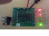
I used an Arduino Uno and the Velleman WPK05/WPSH05 board (see photo).
The WPK05 has one drawback: it has only 6 outputs. Therefore no pedestrian lights are available. It has also 6 digital inputs, which is adequate for this purpose. A connection diagram for the WPK05 is added as pdf.
Other shields may offer more outputs. For a complete installation 8 outputs and 6 inputs are needed. In that case the IO-definition in the sketch must be changed accordingly.
trafficlights.zip (3kb)
trafficlights_con.pdf (19kb)
robvh 2 jaar geleden
Starting expanding the ladder program I came to the conclusion that this was too complicated for me. Maybe because I am a bad ladder programmer (true!), maybe because this is not the best application to program this way (??). Therefore the whole traffic light control was rewritten in the C-language and the manual mode was added to the C-program. The program uses a state-machine, in which every combination of lights is one step, and a timer in an interrupt-routine to determine the duration of every step.
Compared to the original design 3 additional inputs are needed: 1 to switch between automatic and manual mode and 2 for the buttons. The third button for pedestrians is already present from the original version. As you can see I used input 3 for the switch and inputs 6 and 7 for the buttons. Not for any electrical or software reason, but only because mounting the buttons on my test device was easier that way.
Operation is as follows: in manual mode all lights are red and stay that way until one of the buttons is pressed. Then a part of the automatic cycle is started to give this person green light for some time (8 seconds). If everything is safe again (6 seconds or more of all red) the next one can have green light. Originally there was a flaw in the program: there was a fixed priority for the buttons, so if two buttons were pressed allways the same one had green licht first, independent of the order in which the buttons were pressed. Therefore a FIFO (first in, first out) is added to the program. Now the keypresses stay in the right order. A new keypress can be entered in the FIFO at the end of the corresponding green cycle.
Automatic- and night mode work the same as the original (ladder) version.
traffic628m.zip (4kb)
robvh 7 jaar geleden
If a lot of pedestrians keep pressing the button(s), the rest of the traffic never will have green light.
To prevent the traffic from become stuck the new software version adds a green cycle for one of the roads between two green cycles for pedestrians.
robvh 7 jaar geleden
Four trafic lights are shown for the main trafic (called north, east, south and west) and eight lights for pedestrians (called P1 to P8).
Normally only the lights for the main trafic are operating; pedestrians will see red until S1 is pressed. Then the lights for the main trafic will go to red and pedestrians will have green light for a short time.
The diagram shows the maximum setup. For a simpler intersection you can omit P1 to P8 and S1.
By the way: the diagram is valid for counties where trafic is driving right.
robvh 8 jaar geleden
If you want to program a PIC16F628A chip (or a PIC16F819) for my PLC-board, please don't forget the board doesn't have a crystal-oscillator, whereas the ldmicro-program assumes one. Set the configuration-bits to the correct setting (Internal R/C oscillator, using pins for I/O) or change the second last line of the hex-file from “:02400E00623F0F” into “:02400E00500F51” (for the PIC16F628A).
robvh 8 jaar geleden
To generate the hex-file of the traffic-light and the quizmaster both versions can be used. The new version gives some additional information about registers and bits used. Nice, but not essential for those who are interested in the resulting hex-file only.
I only tested the 4.17 version for my own board with PIC16F628A, so I am not able to give any information about other platforms. Eventually you con pose your question on the forum (http://cq.cx/ladder-forum.pl).
Uwe Zimmermann 8 jaar geleden
OK, forget it - I found the binary package in your forum page...