

Build a 3D Printed Arduino RC Drift Car with a Smoke Effect!
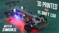
3D print and Assemble an Arduino-based Custom Remote-Controlled Drift Car That Emits Realistic Smoke for Thrilling Indoor Drifting!
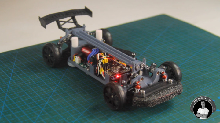
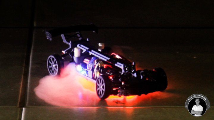
This time, we’re building a 1:24-scale, fully-3D printed miniature RC Drift Car with cool underglow lights and a unique smoke effect. A fun, high-performance Arduino-based RC car that you can 3D print and put together with Arduino-compatible electronics to have a customizable, thrilling indoor drifter, impressing friends and family with your making skills.
Initially, I took inspiration for the details that went into the car’s design from countless different real and miniature scale RC drift cars with the creative addition of LED filaments for the car’s underglow lights and humidifier modules blowing water vapor for the added “smoke effect” when drifting.
The car is controlled with a custom, full Arduino RC system including an Arduino Pistol-grip transmitter seen in the last blog/video which connects to the car’s onboard Arduino-based Receiver to take your inputs and control the car.
It additionally features gear-driven 4-Wheel drive to make sliding quicker as it drifts, full shock suspension to absorb humps and bumps, proportional hobby-grade controls for adjustable speed and turning, brushless motor system for plenty of power, and more which adds up to a high-performance little RC car.
1. Supplies and Resources
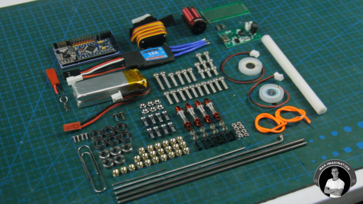
Components and Materials List:
Car Electronics:
- (x1) Rocket RC 3500KV Brushless motor - https://amzn.to/3Sceuhm
- (x1) 18A Bidirectional Mini Brushless ESC - https://amzn.to/4cOzN0C
- (x1) 9G Metal Gear Servo Motor - https://amzn.to/4bQYecv
- (x2) Humidifier Module with Power Module - https://amzn.to/3YdShmU
- (x2) Red LED Filament Wire - https://amzn.to/3WgkiaC
- (x1) 7.4V (2S) 550mAh LiPo Battery - https://amzn.to/46b7yqv
- (x1) 7.4V (2S) Lithium Battery USB Charger - https://amzn.to/4f80D5z
- (x1) JST connector pair - https://amzn.to/3zUi9dq
- (x2) 3-pin female pin header - https://amzn.to/4fpZQgv
- 30-gauge electronic wire - https://amzn.to/3LxwJdf
- (x1) Arduino 8-channel Receiver (See Components List Below)
- (x1) MOSFET Switch for underglow LEDs (See Components List Below)
Arduino 8-channel Receiver:
- (x1) PCB based on Gerber file
- (x1) Arduino Pro Mini (5V 16Mhz) - https://amzn.to/46fJBye
- (NOTE: PCB only matches this version)
- (x1) NRF24L01 Transceiver - https://amzn.to/3ShMSr4
- (x1) AMS1117 3.3V Voltage Regulator - https://amzn.to/4cMJCw9
- (x2) 10μF SMD capacitor & (x2) 0.1μF SMD capacitor - https://amzn.to/3LzKpUY
- (x1) 51K Ohm 0805 SMD V-divider Resistor, (x1) 75K Ohm 0805 SMD V-divider Resistor, & (x1) 10 Ohm 0805 SMD LED's Resistor - https://amzn.to/3LxocqQ
- (x1) Red 0805 LED - https://amzn.to/3y5xTcR
- (x1) Male pin headers: 8-pin (x3) & 4-pin - https://amzn.to/3WsKVdI
- (x1) Female pin headers: 1-pin, 4-pin, & 6-pin - https://amzn.to/4fpZQgv
MOSFET Switch for underglow LEDs:
- (x1) SI2300 N-channel SMD MOSFET - https://amzn.to/3zZuOeN
- (x1) 1002 10K Ohm SMD Resistor - https://amzn.to/3WwDceT
- (x3) 2K Ohm 1/4W Resistor & (x2) 220 Ohm 1/4W Resistor - https://amzn.to/3WsJ2hg
- (x1) 20x9mm (Cut) Perforated Board - https://amzn.to/3W9Abjf
Mechanical Car Parts:
- (x4) Shock absorbers - https://amzn.to/3WfM872
- (x6) 10x6x3mm Ball Bearing - https://amzn.to/3y9GueD
- (x5) 9x5x3mm Ball Bearing - https://amzn.to/3zST9TO
- (x8) Metal Hex Ball Screw - https://amzn.to/3y3P12I
- (x2) M2 4mm screw, (x2) 6mm screw, (x4) 8mm screw, & (x4) nut - https://amzn.to/3WeCLEp
- (x6) Stainless steel M3 6mm screw, (x12) 10mm screw, (x4) 12mm screw, (x2) 16mm screw, & (x8) nut - https://amzn.to/4ff1C3C
- (x27) M3 threaded inserts - https://amzn.to/3WGdAMN
- (x1) 1mm-diameter Jumbo Paperclip (Wire) - https://amzn.to/4f9afwP
- (x4) 10mm piece for upper swing arm links
- (x1) 52mm piece for steering link
- (x1) 20mm piece for servo link
- (x8) 8mm piece for universal joint pins
- (x8) 2.5mm piece for universal joint cube side pins
- (x4) 12mm section of 1.2-1.5mm sweet wire - https://amzn.to/4dbmWVW
- (x1) 2mm steel bicycle spoke - https://amzn.to/4bUFFnR
- (x4) 26mm piece for lower swing arms
- (x1-5) Body pins - https://amzn.to/3YctrDH
3D PRINTING:
- (x1) Matte Black PLA Filament - https://amzn.to/4c6wr8g
- (x1) Matte Dark Grey PLA Filament - https://amzn.to/4c8KeLI
- My 3D Printer: Creality Ender 3 V2 - https://amzn.to/45igolH
Project Resource Files (Code, Diagram & Gerber File):
3D model/design of the Drift Car: https://cults3d.com/en/3d-model/game/arduino-1-24-4wd-rc-drift-car-with-smoke-effect-chassis-parts-design
Get your drift car’s parts 3D printed here: https://jlc3dp.com
Get your receiver's PCB made here: https://jlcpcb.com
Car’s transmitter tutorial video: https://www.youtube.com/watch?v=34BDwDulZl0&t=1s
2. Drift Car's 3D Design
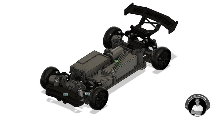
To take you through how I designed the car, I started from obtaining precise dimensions of every single component and modeled them into the 3D design software I use known as Fusion 360.
The modeled parts helped me best visualize and design the chassis with the right measurements to fit them all in and create every single moving part, as well as decorative features to give it the drift car look.
You too can now 3D print the drift car by purchasing its 3D model files listed on my Cults 3D page listed with print settings and more info to guide you on 3D printing out the parts correctly.
3D model page - https://cults3d.com/en/3d-model/game/arduino-1-24-4wd-rc-drift-car-with-smoke-effect-chassis-parts-design
3. 3D Printing Car Parts

Once you have the files, you’ll need to lay them out and prepare the g-code files in your 3D printing software, then begin printing out the parts in 2 batches with the color of your choice.
After 28 hours (+-5h) of 3D printing from PLA and a bit of cleanup, you should be left with wheels, gears, links, axle joints, the chassis, supports, and decorative parts.
However, I do recommend 3D printing/machining parts under tension such as all gears, universal joints, and linking cups from Nylon or Aluminum.
Those kind of parts can be manufactured by JLCPCB: https://jlc3dp.com
For a full description of each 3D printed part with the right material choice, visit the 3D model page linked previously.
4. Melting In Threaded Inserts
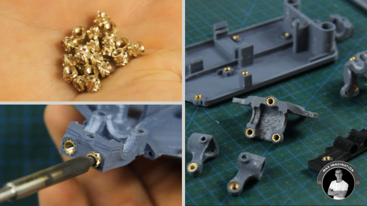
With a soldering iron, we can melt 27 of those M3 threaded inserts into the car parts that need them. Those parts include the Chassis, two Gearbox Housings, Top Supporting Bar, Front Wheel Cups, and the Front Bumper Holder.
Threaded inserts, also known as threaded bushings, are fastener elements that are inserted into objects to add threaded holes for tightening screws/bolts. Think of one like an embedded nut.
5. Installing Drive Gears
Next, we can begin installing the first part of the 4WD drive train which is the rear geared drive mechanism.
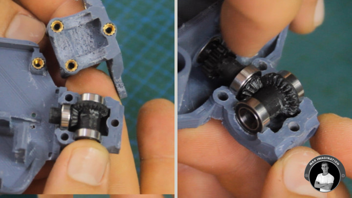
Let’s pop in a 9mm bearing into the chassis to support the drive shaft, then attach two 10mm bearings onto one of those beveled spur gears without a differential, followed by assembling the rear drive pinion gear with a bearing and spur gear attached with which the motor makes contact.
We can then install it and the spur gear positioned with right orientation as shown. Afterward, let’s secure the rear gearbox housing together and install the brushless motor with its pinion gear to wear-in the bevel gears inside which will help make the shaft turn with ease and less friction.
After that, we’ll assemble the front drive gears which take the motor input via a drive shaft which connects to the front pinion gear that is strengthened with superglue. We can then attach bearings onto these gears like the last and put them in place with the orientation of the spur gear in mind so it rotates in the same direction as the front.
6. Creating Drive Shafts
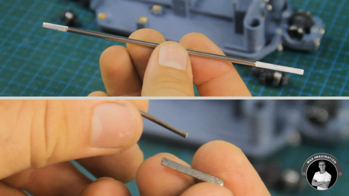
For the drive shaft that connects the front and rear drive gears, we’ll need a 2.5mm stainless steel shaft that is marked so it’s cut down to 124 mm in length and for the front and rear axles, a couple of shorter 19.5mm sections.
With the help of a bench vise, let’s cut these marked pieces of steel to end up with the 3 sections. Using a file, we’ll begin completely filing down the shorter ones into halves followed by marking the ends of the longer rod and filing them down halfway so the flat ends match the lengths of the front and rear pinion gears.
Two tips would be to use an angle grinder to grind down the ends and precise markings to indicate the exact half-moon chunks you need to remove off each end.
7. Installing Drive Shafts
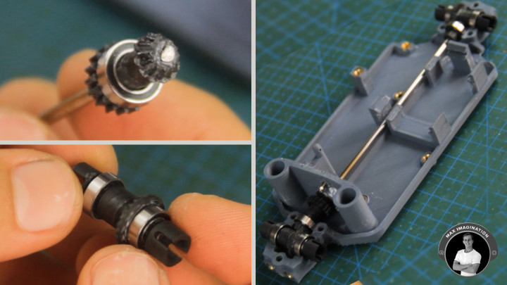
Now, let’s work on installing these axles and the drive shaft into the gears through heating up the rod ends and carefully pushing the rods in without splitting them. However, with the front pinion gear, you may need to first wear-in the connection with another axle and then slide it on with a more loose fit to the drive shaft once it is in its place.
Again, we’ll need to wear in the gears for smoother rotation now having the front ones installed.
For the front and rear axles, we’ll push or hammer in a shorter half-moon cut rod into each spur gear so a 3D printed input shaft cup can firmly connect to each end. However, I still recommend securing these on with the addition of superglue.
8. Assembling Gearboxes
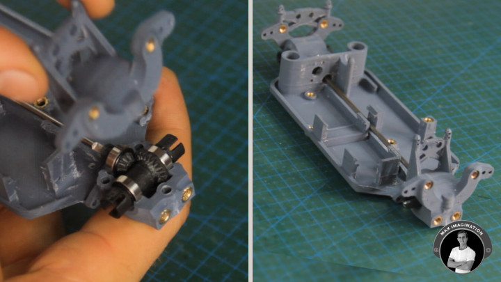
Now, these two can be secured into their gearboxes with the corresponding upper housing pieces closing them up with the help of some M3 screws.
I do recommend first checking that the bearings are not squeezed too tight to turn nor too loose to be held depending on the print quality. For mine with lower print quality, I had to do a bit of sanding/scraping at the bearing holders in each part of the gear box for them to fully close.
A tip to throw in, would be to grease the gears if there is too much friction at play between gears. Petroleum Jelly or a well suited gear-greasing solution will do the trick.
9. Mounting Lower Swing Arms
Next up, let’s install the swing arms which are designed to help hold the wheels.
We’ll need to make the two fork pieces that secure them which consist of a tab with a couple of 2mm bicycle spoke pieces of 26mm pushed into each. With the help of each rod, the swing arms can slide on to the fork parts and then into the chassis with M3 bolts.
However, the front fork gets secured with the front bumper holder using the longest bolts in your M3 screws kit. Keep in mind that it needs to be installed with the flat side facing up.
10. Installing Wheel Cups
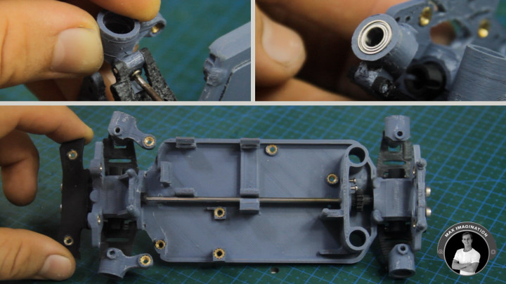
Now, we can install the wheel cups which hold the wheels through bearings. We have two for the rear and two for the front which hinge side to side.
Let’s cut a 10mm section of 1.5mm sweet wire/craft wire rod for each wheel cup. Each rod gets pushed in and is secured with superglue within the wheel cups themselves to allow them to hinge up and down.
We can then push in the smaller 9mm bearings into the wheel cups with a tight fit.
11. Making Universal Joint Axles
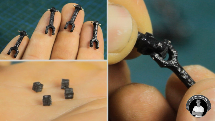
For the universal joint drive shafts, if made out of PLA, each one of these dogbone-looking pieces needs to be fully coated in superglue to prevent the hazard of it breaking when under tension. For a good length of time, you may get away with using this superglue technique to preserve all parts that turn if you print them with high quality, fresh PLA filament.
Then we can cut an 8mm section of paperclip wire which gets pushed into its ball hole for grip.
From here, with some more paper clip wire, we can adjoin the dogbone piece with the wheel-connecting part of the joint through one of those little cubes. The dogbone takes a full-length piece of wire holding the cube, while the other joint piece connects with 2 shorter pieces of wire pushed into the cube, forming the universal joint. Each wire end can then be superglued to stay put.
Now we repeat this 3 times to have 4 complete universal joint axles which allow for rotation while bent at different angles.
12. Installing Axles
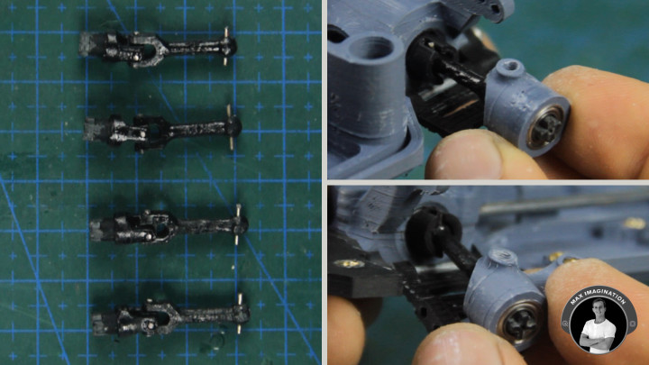
We can now connect the input shaft cups to the bearings through the newly installed universal joint axles. With these installed, the central drive shaft can transmit its rotation to the wheels and the axles should all rotate smoothly.
To prevent axle wobble within the bearing when a wheel is installed, we can secure the protruding part of the axle with its wheel-connecting cross to the inner part of the bearing with superglue. Alternatively, we can rely on a tight fit if possible.
13. Assembling Upper Swing Arms
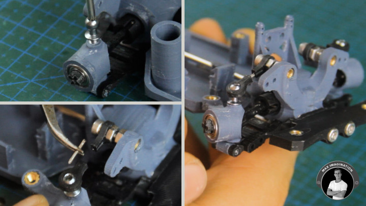
To create the upper swing arms connecting the wheel cups from above, we’ll need 4 of these 4.8mm ball head screws with their threads cut halfway up, sanded, and installed in the wheel cups while allowing the axles to spin.
The upper part of the swing arm consists of an M3 bolt, swing arm piece, and a couple of nuts. Two of these units screw into each of the gearbox housing arm pieces. Alternatively, you can instead use those ball screws in place of the nuts and bolts.
For the outer part of the swing arms, we’ll need four of these 3D printed ball cups that’ll connect to the ball screws. Each one can be worn in to rotate easier by turning each one on a ball screw that has been heated.
For the linking part to finish the upper swing arms, we’ll glue 10mm sections of paperclip wire.
The wheel cups should now be able to stay fixed vertically while moving up and down or when turning.
14. Adding Shock Absorbers
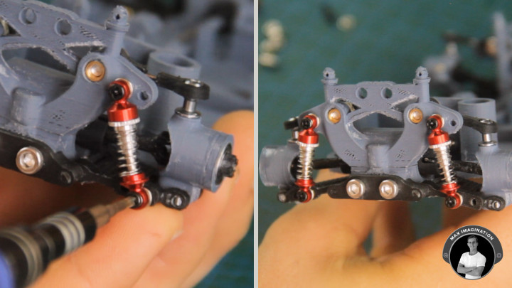
For the shock absorbers, we’re using four of these tiny, 26mm 1:28 scale RC car shocks which take the included spacers and M2 screws, then get secured to the chassis onto either of the two hole pairs in each spot, attaching the lower swing arms to the upper chassis arms. For the shocks to stay well secured, I recommend using longer M2 screws with nuts.
These specific shocks don’t take oil. If oil-filled, they will leak and make a mess! In this case, it’s much better to keep them dry or invest in alternative shocks that can hold oil.
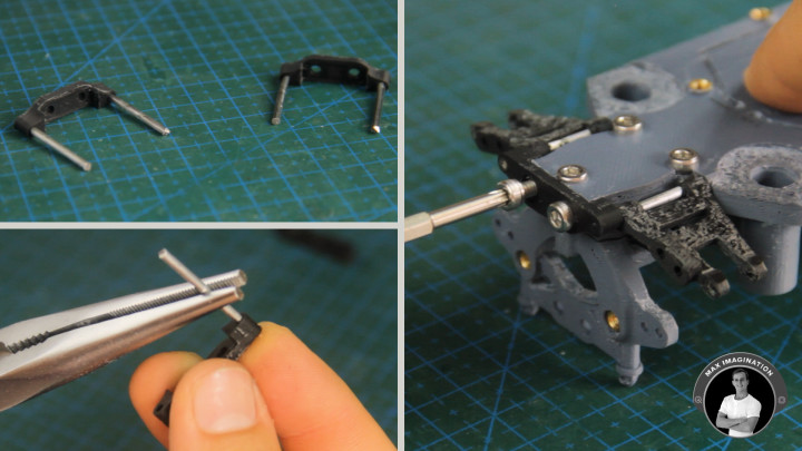
15. Linking Steering Mechanism
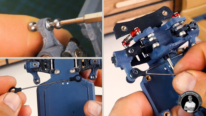
To complete the steering mechanism, let’s take 3 of those ball screws, sand off enough of two of them to fit into one wheel cup and one whole ball screw for another cup’s arm.
We can then make the steering link piece which consists of the right length wire and two ball cups which link the two ball screws below.
With some spare paper clip wire, we’ll make the servo link which clips onto the only ball screw sticking up. It’s better to cut off a little more than you think you need, so there is room for the servo link’s distance adjustment.
16. Installing Servo Motor
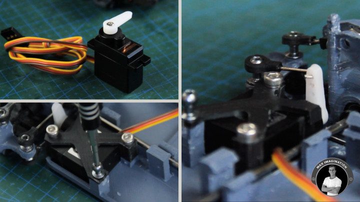
Now comes the time for installing motors.
Starting with the servo motor, since this stock metal-gear servo doesn’t fit into the chassis, we’ll need to clip off the two tabs to then make it fit. We can follow up with the servo mounting piece which screws on with a couple of bolts and a ball screw.
Then the servo link can get attached to the servo horn at the right distance apart from the left wheel cup with everything pointing straight.
The servo link can actually be adjusted a notch up the servo horn for a wider range of steering if you’d like.
17. Installing Drive Motor
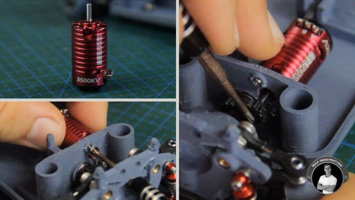
For the drive motor, we’re using this Rocket RC Mini 3500KV Brushless inrunner motor which we’ll secure to the chassis with a couple of short M2 screws followed by sliding on its 3D printed pinion gear onto the chamfered shaft with a tight fit. For the longest lasting pinion gear, I recommend having it made from brass or aluminum. Nylon can work too as a second-best option.
Alternatively, you can in fact use a brushed motor instead of the brushless one if you’re looking for a more affordable option. Keep in mind that you’ll sacrifice some power efficiency in making the switch, so I then recommend using the best type of brushed motor of this size which is an original/high quality brushed 3-9V 180 motor that you can find on sites like Amazon.
18. Installing Parts for Smoke and Glow Effect
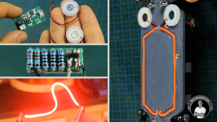
Now for the “smoke effect”, we’re using a couple of these humidifier modules which emit water vapor from these foam sticks that absorb water. They are quite interesting components to play around with!
To set them up, we’ll begin by soldering wires to their power module, one for power (5V), another for ground (GND), and the white one for signal (HIGH/LOW) so we can remotely trigger the module with its humidifiers to turn on.
The humidifiers themselves first need their wires desoldered and reinstalled through the chassis of the drift car, so the connectors protrude from the top side.
Then, we can super glue them with the emitting sides facing out.
For the underglow effect, we’ll be using a couple of LED filament wires or LED strips in wire form that light up. We’ll take the pins with the holes and pull each of those through the bottom part of the chassis and glue the ends with only the pins poking out at the surface. Then, we’ll glue the LED filament to sit in the tracks and finish off by repeating what we did before by gluing the other end. We then repeat this for the other wire.
At the surface of the chassis we should have the cathode and anodes of the LEDs sticking out.
Afterward, we’re going to wire the two water vapor modules together in parallel with one connector.
And then do the same thing with the LED filaments, wiring them in parallel only with a wire coming from each end. These LED wires get quite bright at only 3V!
Next, we can secure the humidifier modules’ power supply with the shortest screws possible.
For powering the underglow LEDs, we’ll need to make a custom LED driver circuit that allows us to control the on/off status which consists of an SI2300 N-channel MOSFET and an SMD 10K Ohm pull-down resistor with three 2K Ohm and a couple of 220 Ohm, quarter-watt (1/4W) current limiting resistors soldered onto a small perforated board.
The LED’s resistors just get soldered in parallel to form a higher-watt (1.25W) current-limiting resistor followed by a wire to connect the LEDs, another for ground, and the white one for signal.
After trimming the board, it should look more or less like this. Here’s a good reference image to clearly see the connections. The LED control board can then be double-sided taped to the chassis and have the cathode LED wire soldered on board.
19. Installing ESC
After a bit of wire management, we should have 3 wires sticking out from the LED board and 3 from the humidifier’s power module that we installed previously.
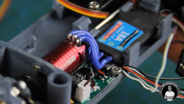
To control the motor, we’ll need a bidirectional brushless 2S ESC that can handle 18 Amps or double the current output of the installed motor
We’ll simply need to replace its power connector to instead match the one on the battery and then pop it into the chassis where it’s designed to sit.
Then, we’ll solder the 3 wires in order to the motor’s terminals. The outer two can actually be swapped to reverse the motor’s rotation if needed.
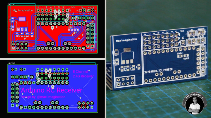
20. Making Arduino Receiver (PCB)
In terms of circuitry, all the car needs now is the receiver.
To get your hands on the PCB’s gerber file, click the link to the project resources at the top of this blog to access the project files folder which includes the free, downloadable gerber file of the receiver PCB. I designed it to simplify the making process so you don’t need to worry about connections and instead only focus on soldering the components to achieve a complete receiver.
As with the other parts and components for this project, you can find all the components and pins listed with product links at the start of this blog.
21. Assembling and Connecting Receiver
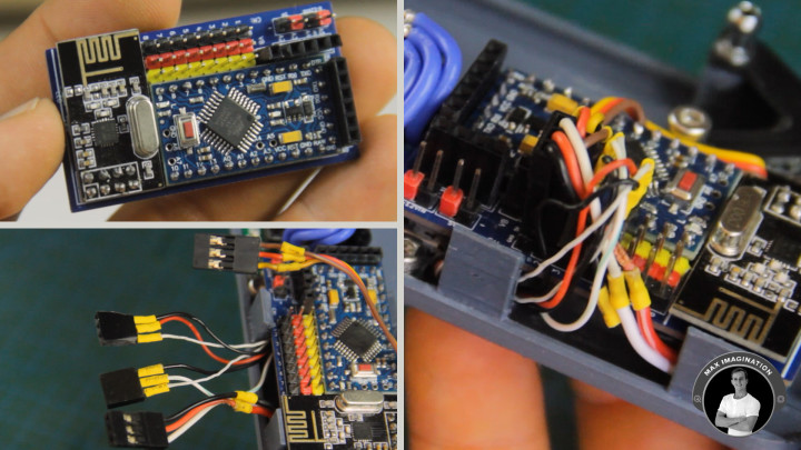
Normally, when soldering SMD components onto a PCB, you’d use solder paste, but as I didn’t get some prepared, I instead used solder flux as paste and soldering tin with my soldering iron to bond the components while holding down each one with a pair of tweezers. This is a slower, yet alternative way to solder PCBs if you don’t yet have the right kind of equipment to do so.
With the surface-mounted components in place, we can begin installing the Arduino Pro Mini, NRF24 Radio Transceiver, peripheral pin headers, headers for voltage monitoring, analog inputs, power inputs, and female headers for programming.
And after a bit of soldering and pin clipping, we have a receiver!
The Arduino receiver is programmed using the Arduino IDE on a PC, via an FTDI USB to Serial Converter connected to the 6-pin female header on the board.
The receiver and transmitter code with more info can be found in the project resource files folder and is discussed in more detail in a previous blog/video about the Arduino Pistol Grip Transmitter.
Once programmed, the receiver can be clipped into place on top of the ESC without adhesives.
To wire it, we’ll first give the appropriate pin headers to the sets of wires from each module, shorten any if needed, and then plug these into the receiver’s headers starting with the ESC on channel 1, servo on channel 2, then the LEDs and the humidifiers connect to any channels from 5 to 8 (Currently connected on CH5 and CH7).
22. The Battery
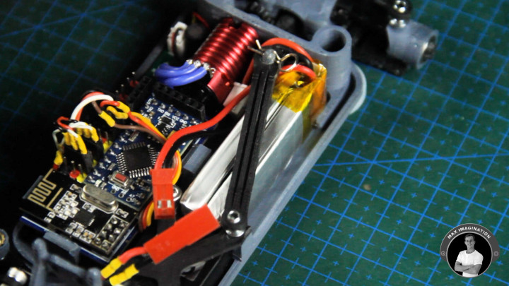
Next, we can mount the 2-cell, 7.4V 550mAh LiPo battery held down with the clip and body pin.
If you plan to use a more powerful battery, such as a 3S (3-cell) or higher, make sure the motor you select can handle the increased voltage. For this RC car with its current motor, the maximum battery configuration you can use is a 2S.
This battery lasts the car running 10 to 15 minutes on a full charge with all elements going at once.
23. Car Wiring Diagram
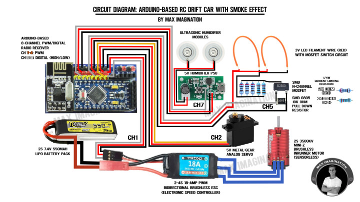
To ensure precise connections, it is crucial to follow the tutorial above and refer to the circuit diagram, especially if you are using the same components for this Arduino RC Drift Car.
Be sure to pay close attention to the wiring at each step of the drone's circuit assembly, particularly the LED driver circuit.
24. Final Parts Assembly
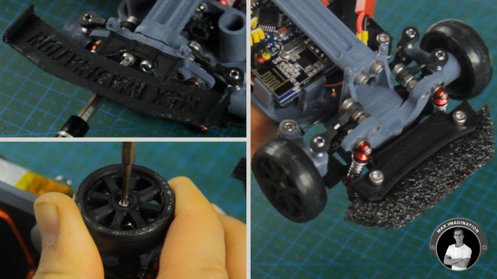
For both looks and stability, let’s install the car’s tail wing and top supporting bar which prevents the chassis from bending at the drive mechanisms to prevent gear misalignment.
Onto the little (X) crosses which poke out through the bearings, we can finally attach the 3D printed wheels, but first, let’s give them a little grip by rolling on some electrical tape and cutting off any excess with a hobby knife. The rubbery feel should give it extra traction on tiles. We’ll also do up the other wheels with the same method.
With the connecting feature of the crosses, we can pop on the wheels and secure them from falling off with some small 6-8mm-long screws.
As an optional preventative measure, let's cut out a front bumper from some foam and sandwich it between the bumper plates to protect the car from collisions. The denser the foam used while remaining subtly squishy, the better.
25. Loading Humidifiers for Smoke Effect
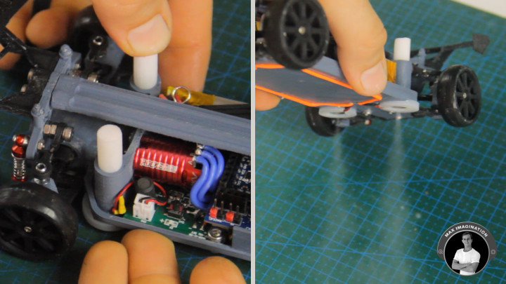
To load up the modules which create the “smoke effect”, let’s cut up some 3-centimeter sections of the foam stick that came included with the humidifiers, soak these pieces, and push them into the cylinders which were 3D printed to hold them with a tight fit.
Ideally, it is best to keep the rear end of the car raised as high up as possible to make room for the humidifiers to form the water vapor which is then seen out the back. The car can be raised by adjusting the position of the shock absorbers to mount onto the innermost screw holes.
26. Pairing Up The Arduino Transmitter
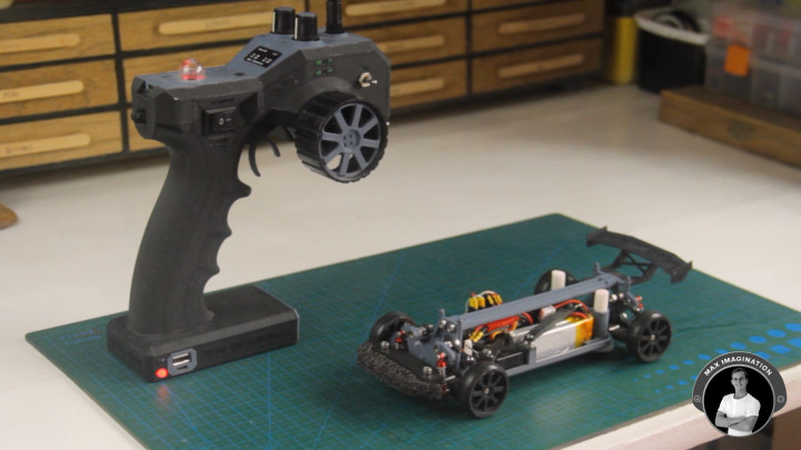
Now the drift car is complete!
If you ever want to give the car a body shell for protection/decoration, you can clip one on using body pins clipped onto those standoffs with holes at the top of the car.
The transmitter which controls the Drift Car is also Arduino-based, comes in pistol-grip form, with a throttle trigger, steering wheel, potentiometers, toggle switches, and a total of 8 channels of control inputs, well suited to operate the car and its unique added features.
To build it, you may watch the full video tutorial of the Arduino Pistol-grip Transmitter with more info here: https://www.youtube.com/watch?v=34BDwDulZl0&t=1s
Pairing the Arduino transmitter to the car is straightforward, you simply switch it on and it automatically binds with the turned-on car.
Since the “smoke effect” modules are connected to channel 7, you flick the lower toggle switch to turn them ON and twice up and down to turn them OFF due to how their power supply control board is programmed.
Knowing the underglow LEDs are on channel 5, the upper toggle switch takes care of turning them ON or OFF.
Before we give the car any drive tests, let’s charge up its battery through the 3-pin header connected to a (2S) Lithium Battery USB Charger.
27. Drifting The RC Drift Car
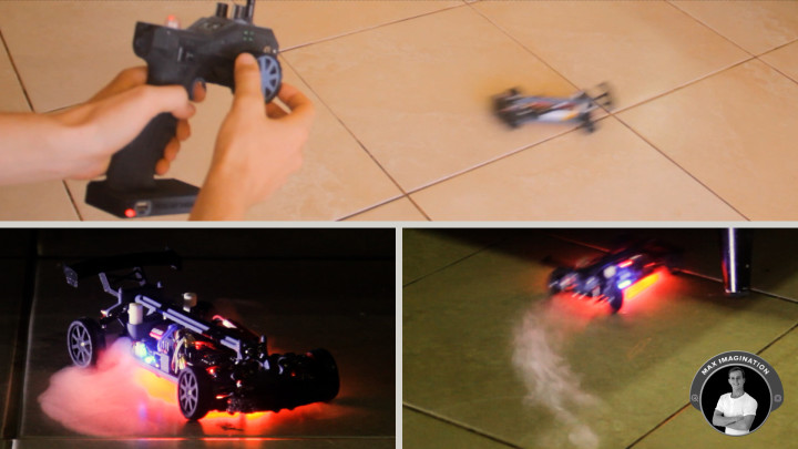
To perform a drift with the RC car, you turn the steering wheel in the direction you want the car to go as you’re hitting the throttle and immediately turn the wheel the opposite way to make it slide sideways as it turns. For this to work, you need to make it drive at a higher speed and skid its wheels. It may seem tricky at first, but you will eventually get the hang of it.
With a control range of up to 100 meters with the Arduino receiver and 10-15 minutes of battery life, the car gives you plenty of room and time to have fun drifting around.
28. Troubleshooting Tips and Key Takeaways
1. Ensure Proper Supply of Power:
- Pitfall: Insufficient power can lead to inconsistent performance or failure to power up.
- Solution: Use a multimeter to check voltage levels before using the car and ensure all connections are secure.
- Tip: Verify that your battery is fully charged and supplying the correct voltage to all components.
2. Check Component Compatibility:
- Pitfall: Incompatible components can cause malfunctions or damage.
- Solution: Double-check component specifications and cross-reference with the Arduino compatibility list - ask me if in doubt.
- Tip: Ensure all electronic components are compatible with each other and with the Arduino board.
3. 3D Printing Quality:
- Pitfall: Poor print quality can lead to parts that don't fit or break easily such as in some areas of my car.
- Solution: Regularly maintain your 3D printer, use appropriate print settings, and consider printing critical parts in stronger materials like Nylon or Aluminum.
- Tip: Use high-quality PLA filament, ensure your 3D printer is properly calibrated, use a filament drier to counter the effect of humidity on prints, and strengthen parts under tension such as swing arms by coating them in superglue.
4. Accurate Assembly:
- Pitfall: Misaligned parts can cause mechanical issues and hinder performance.
- Solution: Take your time during assembly, and if needed, refer to detailed images or the YouTube video tutorial for clarification.
- Tip: Follow the assembly instructions carefully, paying attention to the orientation of parts.
5. Soldering Technique:
- Pitfall: Cold solder joints can cause intermittent connectivity issues and potentially lead to damage of the components from joints touching or coming off.
- Solution: Use a quality soldering iron, flux, and ensure each joint is shiny and well-formed.
- Tip: Use proper soldering techniques to ensure strong and reliable connections.
6. Drive Shaft and Gears Installation:
- Pitfall: Misaligned gears or slightly bent shafts can cause excessive wear and reduce efficiency. Gear material may be too weak, causing quick wearing of gears.
- Solution: Check for smooth operation after assembly, adjust as necessary, and print your gears from nylon or metal.
- Tip: Ensure drive shafts and gears are properly aligned, secured, and use a full metal drive train making all rotating parts under tension from aluminum/brass.
7. Motor and ESC Configuration:
- Pitfall: Incorrect ESC driving via the Arduino’s PWM output can lead to poor motor performance (unwanted vibration/stuttering at low RPM) or damage.
- Solution: Refer to the ESC manual for proper configuration, calibrate the ESC, and try adjusting PWM delay in the code until the stuttering disappears.
- Tip: Match the ESC to the motor specifications (Double the amperage of the motor’s maximum amps at full throttle) and ensure correct wiring.
8. Underglow LEDs and “Smoke Effect” Modules:
- Pitfall: Faulty LEDs or humidifiers can detract from the visual effect.
- Solution: Verify functionality with a temporary setup before securing them in place.
- Tip: Test the LED and humidifier modules before and at some point during installation.
9. Testing and Calibration:
- Pitfall: Skipping tests can lead to undetected issues that are harder to troubleshoot later.
- Solution: Perform incremental tests during assembly and a full test run after completion.
- Tip: Thoroughly test the car in a controlled environment to ensure all systems are functioning correctly.
10. Programming the Arduino:
- Pitfall: Incorrect or different code used than what’s provided can cause erratic behavior or no response from the car.
- Solution: Double-check the code for errors, use the serial monitor to debug errors, and ensure proper communication between the NRF24 transmitter and receiver.
- Tip: Use the Arduino IDE from your computer to upload the correct code to both the transmitter and receiver.
11. Regular Maintenance:
- Pitfall: Neglecting maintenance can lead to premature wear and unexpected failures.
- Solution: Clean gears, grease gears, check for loose screws, and inspect electronic components periodically.
- Tip: Perform regular maintenance checks to ensure the car remains in optimal condition.
By following my troubleshooting tips and key takeaways, you'll be better equipped and ready to build and maintain a high-performance 3D-printed RC drift car, making sure you face a smooth and enjoyable experience.
Conclusion
Building a mini 3D printed RC drift car comes down to getting a few key details right, from making sure the power supply and parts work together to nailing the 3D print quality and putting everything together perfectly according to the instructions.
By following the troubleshooting tips above, you can avoid common problems and end up with a unique, RC drift car that gives off the visual effect of it doing burnouts! With minor changes such as metal gears and axles, the final product is a fully functional, long-lasting custom RC drift car that shows off your technical skills and creativity of using unconventional components to give it a realistic look when drifting.
Once again. All resource files made to help you start building the project can be found at the top of this blog.
Want to see the whole build process in video form and get to see the drive tests? Check out the full video! Click the embedded video below to watch it now and get good at building RC cars!
Discussie (0 opmerking(en))