
Decade Tube Counter
After a long experience with digital circuits, I wanted to build a 4-bit counter using only tubes and display the counter values on a Nixie tube. The knowledge about digital circuits based on tubes is slowly getting lost. This article shows how I built the circuit and what I learned from it.
Motivation:
After many years of working with hardware designs based on digital semiconductors, it was time to realise a very old idea. My idea was to build a 4-bit counter with tubes and display the counter value on an old Nixie ZM1042 digit tube. The knowledge of digital circuits based on tubes is slowly being completely lost.
Realisation:
The start of the development came from a video by Usagi Electric about the decade counter AC-4G from Hewlett Packard from 1956, see https://www.youtube.com/watch?v=WrBPVVKvWfE
The manual for the counter shown in the video can be found on the Internet. It contains the circuit diagrams of all variants of the counter including a detailed circuit description and diagrams of signal curves for servicing purposes.
For price reasons, I did not realise the flip-flops with double diodes 5963, which Hewlett Packard used, but with tubes of the type E90CC and E92CC. These tubes were developed by the company AEG especially for counting circuits. You can still easily buy these tubes and get the data sheets for them.
A counter with four flip-flops has 16 different states. For the Nixie tube, the counting sequence must be limited to 10 states. This is achieved by two feedback loops at the flip-flops. This results in the following 10 state patterns:
1: 0 0 0 0
2: 0 0 0 1
3: 0 0 1 0
4: 0 0 1 1
5: 0 1 1 0
6: 0 1 1 1
7: 1 1 0 0
8: 1 1 0 1
9: 1 1 1 0
10: 1 1 1 1
The state sequence is no longer binary due to the feedbacks, but this does not matter in the design because at the end 10 digits should light up one after the other and the patterns are decoded accordingly.
In principle, flip-flops consisting of double triodes can be switched via pulses to the anode, the grid electrode or the cathode. In this case, switching for counting takes place via low pulses to the anode. In contrast, the feedbacks switch the flip-flops via pulses to the grid electrodes.
Optocouplers are used to decode the 10 states to control the numeric tube. Decoding with pentodes or heptodes would have meant 10 additional tubes. Optocouplers with CTR > 1000% @ 1mA are used so as not to influence the anode current too much.
A classic Abraham-Bloch multivibrator is used as the 1 Hz clock source for the counter, also realised with an E92CC double triode.
Before the first assembly, the circuit was simulated with LTSpice. The simulation is based on an LTSpice model of the 12AX7A (ECC83) tube, which I downloaded from the website http://www.duncanamps.com/spicevalvest.html. The Spice model does not exactly match the E90CC and E92CC tubes used, but with the help of the simulation it was still possible to dimension the circuit of the tubes in principle and I was able to check the behaviour of the flip-flops when changing the resistors and capacitors.
As the main design goal was about the tube circuit, the power supply was kept simple. An old laptop power supply with 19 V output voltage serves as the energy source. An integrated DC/DC converter is used to generate the heating voltage for the tubes. Each tube requires 400 mA. Around 170 V at 8 mA per tube is required for the anode voltage. There was no ready-made solution available for this. I therefore used a project with the TL494 switching regulator from Elektor June 2014. A small toroidal core with a turns ratio of 1:9 forms a transformer for 7 W output power. Since the power requirement of the circuit is almost constant and the tubes are rather tolerant to changes in the anode voltage, I have built the circuit simply, without feedback to regulate the output voltage.
A PCB was realised for the complete circuit, which worked almost straight away thanks to the previous simulation. However, the flip-flops initially only had 6 states instead of the planned 10. The second flip-flop behaved like an inverter and switched on rising and falling edges. After some measuring and thinking, I realised that I had calculated the circuit for E90CC type tubes but then bought the cheaper E92CC. Both types have slightly different characteristics. This still worked with 3 out of 4 flip-flops. After replacing the second tube with an E90CC, the circuit now works as planned and I didn't have to replace the other tubes. With the 170 V power supply, there were problems with the material of the toroid core and the MOSFETs used. Both could be solved by replacing the components.
Conclusion:
Now around 20 W of power is converted into heat in a circuit that only lights up 10 digits in succession. The whole thing is relatively pointless, but it was fun to familiarise myself with the topics of digital circuits with tubes and the development of the high-voltage power supply with push-pull converter and transformer. The design leaves room for improvement. The circuit should be calculated for the E92CC tubes used and the high-voltage power supply should be given a feedback to make it independent of the input voltage. This can be improved with the next tube circuit.
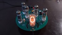
The short video shows the behaviour of the finished assembly. If you are interested, I will be happy to pass on the design and PCB data.
Updates van de auteur