

Dimmbare Aussenbeleuchtung / Dimmable Outdoor Lighting [140574]
Some time ago I’ve installed in the roof over the terrace four LED spots. Unfortunately, the brightness of the four spots (2.8W each) was much too bright for us.
Note: in the updates you'll find a new schematic and PCB (V2.2), new versions of firmware and PC application
for the english version please scroll down...
Hallo, ich möchte euch hier gerne mein Projekt vorstellen.
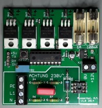
Ich habe vor einiger Zeit auf der Terrasse 4 LED Spots in den Dachkasten eingebaut, leider mussten wir dann feststellen, dass die 4 Spots (je 2,8W) viel zu hell waren. Aus diesem Grund wurden die LED’s auch so gut wie nie angeschaltet (wer sitzt schon abends mit einer Sonnenbrille auf der Terrasse). Irgendwann kam mir dann die Idee, die LED’s zu dimmen (in der Anleitung steht zwar nicht dimmbar), aber da die LED‘s 12VDC benötigen sieht die Chance gar nicht so schlecht aus. Dann habe ich schnell das Steckboard raus gekramt und ein paar Bauteile zusammen gesucht. Anschließend habe ich eine Schaltung zusammen gesteckt. Ich habe mich beim Versuch für ein µC entschieden, da dies die schnellste Variante war, die LED’s mit PWM anzusteuern. Und siehe da die LED’s lassen sich doch dimmen. Während den Experimenten kam mir dann die Idee, die Schaltung so zu ändern das der Dämmerungsschalter die Schaltung mit 12VDC versorgt und die LED’s mit einem Tastgrad von 10% leuchten. Wenn dann ein Bewegungsmelder eine Bewegung erkennt wird (fast) stufenlos auf 50% hoch gedimmt und bei verlassen wieder zurück auf 10%. Beide Werte sind individuell über UART einstellbar und bei Versuchen hat sich herausgestellt das 10% und 50% optimale Werte bei unseren LED’s sind. Jetzt haben nicht nur die LED’s die optimale Helligkeit, es wird auch noch Energie gespart. Wie schon beschrieben, schaltet der Dämmerungsschalter die 230VAC für das Schaltnetzteil und die 12VDC versorgen jetzt die Schaltung und die LED’s. Die 12VDC wird dann auf 5VDC (IC2) für den Logikteil herunter geregelt. Der µC arbeitet mit einer Frequenz von 200kHz und erzeugt damit eine Frequenz von 150Hz für die PWM. Benutzt wird nur ein PWM Ausgang der die 4 Logik-Level MOSFET’s ansteuert (ein MOSFET pro Lampe). Das Programm wurde mit „mikroBasic PRO for PIC“ von „MikroElektronika“ entwickelt. Die 230VAC vom Bewegungsmelder werden galvanisch über den OK1 (Optokoppler 4N28) getrennt und auf einen Eingang vom µC gelegt.
Das Programm für den µC ist so klein, dass es mit der Demo-Software von MikroElektronika bearbeitet werden kann. Zusätzlich habe ich mit "Visual Basic Express" eine Software entwickelt mit der man über UART die Werte übermitteln kann.
Optimierungen:
Die Schaltung ist so ausgelegt, dass ich ein Großteil der vorhandenen Bauelemente verwenden konnte. Optimaler wäre sicherlich der Optokoppler PC814, anstelle vom verwendeten 4N28, dann hätte man sich die Diode D1 sparen können (siehe http://www.mikrocontroller.net/articles/230V). Für den verwendeten µC PIC16F628 hätte auch ein PIC12F gereicht bzw. wäre dieser Zeitgemäßer. Für die MOSFET T1 – T4 hätte man auch SMD Varianten nehmen können. Alles zusammen hätte für ein wesentlich kleineres LP-Layout geführt. Ich habe die Leiterplatte so entworfen, dass diese in eine Aufputz-Abzweigdose passt (in meinem Fall 85x85mm), aber beim klemmen habe ich gemerkt, dass ein paar mm mehr Luft besser gewesen wären.
_____________________________________
EDIT:
_____________________________________
EDIT:
_____________________________________
EDIT 03/31/2015:
Hi i changed the firmware for the µC and i have a problem now.
I removed the "delays" (for dimming time) and added a simple addition for this function. This is working well, but i have a problem to setup the values via uart.
I'm sending a data string from the windows programm to the µC via uart and the µC receive the string but chronology the is wrong.
I don't understand why because i use a uart receive interrupt.
This is a example for the data string:
start_byte | percent_low | percent_high | dim_up | dim_dn | end_byte
250 | 10 | 50 | 10 | 20 | 200
The new windows program and µC firmware is added below.
I hope someone understand my problem and can help me.
with regards
EDIT 03/31/2015:
_____________________________________
µC project and Win Software added
µC project and Win Software added 03/31/2015
Discussie (6 opmerking(en))

JohnHind 8 jaar geleden
You could either use a larger microcontroller with a PWM for each of the four MOSFETS giving separate brightness control, or four separate 1 channel devices each with its own microcontroller mounted close by the lamps to reduce the RF issues aluded to in the article.
But with the current design, unless I am missing something, you could save BoM costs by just fitting one MOSFET and connecting all four lamps in parallel to that.

AndiM 10 jaar geleden
Hi B.Chabb
you right with the Pic16F628A but i use the Pic16F628.
And i use the ER-mode you find it here: DS40300C-page 94.
Hi Clemens,
I'm sorry for my mistake, I added the old and new µC project.
And I added the source code for the windows program.
I checked the transmitted data string (from Win Prog to µC) with a second uart/usb converter on rx pin of the µC and the string is correct.
But you're right with the byte 1 and 5, i changed it.
I clear now byte 1 and byte 6 and it will work.
Without these changes it will work only one time (after µC reset)
thanks Clemens
with regards
AndiM

ClemensValens 10 jaar geleden
It is not easy to understand what the problem is and why things may go wrong because you don't provide a lot of information and source code. For instance, how do we know that your Windows program is OK? Also you don't say what you changed and even if you did, the old working version is not available.
Anyway, looking at the file 'aussenbel.mbas' I noticed that you check for bytes 1 and 6 as sentence markers, but you clear bytes 1 and 5 when youare done. So, as soon as you start sending a new sentence from your Windows program a complete sentence with old data may be recognized. Maybe this explains your chronology problem?
Regards,
Clemens
AndiM 10 jaar geleden
I'm sorry I want to add my post here,
Hi Clemens,
R2 is to setup the MCU clock to 200kHz.
The oscillator mode is 'ER' (external resistor) with 1M.
I need this setup get a correct frequency for uart.
I added a simple e-plan (as photo)
This circuit is a stand alone circuit but if you need another brightness as 10% (twilight switch is on) or 50% (motion detector detects someone) you can setup it via UART.
sorry my english isn't the best
regards,
AndiM

Lucky 8 jaar geleden
I work in the Elektor Lab and need this new version to prepare it for publication in our magazine. It will be posted here anyway, if you could be so kind to post at least the schematics for now... I would also suggest to add an ISP (PicKit) connector to the board.
Best regards,
Luc
AndiM 8 jaar geleden
you're right with the PIC16F628. But I had a lot of these PIC's in my private stock, because this was my first PIC.
I made a new version with PIC12F1840. I don't published the new version because elektor will publish this project in elektor magazine.
I don't have a publishing date.
regards
AndiM
Lucky 8 jaar geleden
But why do you want to tune the oscillator frequency to match with the UART's baudrate? In my experience the PIC's internal oscillator is accurate enough for stable serial communication.
Regards,
Luc
ClemensValens 10 jaar geleden
Hello AndiM,
Thank you for posting this circuit. However, I am not sure if I understand it all. Looking at the schematic I was wondering what the function of R2 is?
Do I understand it correctly that this circuit is controlled from another circuit that provides the dimming level? Over the optocoupler? What kind of signal is that?
Regards,
Clemens

Idontno 10 jaar geleden
Updates van de auteur
AndiM 8 jaar geleden
This version wasn't testet, because I don't have a PIC12F1840.
I add all source files (schematic, pcb layout, code for mcu and code for vb.net project).
In this version I use the internal clock, but I don't increase the mcu speed. If you increase the mcu clock you increase the program cycle too. That will increase dimm up and dimm down time. With this PIC it is possible to set the baudrate to 4800 bps.
If you want to make changes, you can use the Demo Version of the compiler, because the source code for the mcu is so small.
latest Version for PIC12F1840 (329kb)
latest Version (467kb)
Lucky 8 jaar geleden
I took the liberty to change all parts to through hole mounted types. In this project it doesn't make the PCB much larger, and adding mounting holes gave additional space.
The 1A fuse for the LED spotlights makes sense, but do we really need the fuse for the 5V power supply? I'd rather replace it with a diode as reverse polarity protection for the power supply.
Best regards,
Luc
AndiM 8 jaar geleden
you save a lot of space without the fuse.
In version 2.0 I replaced the pcb terminal block "K1" with a cage clamb from wago. I had problems to connect the wires.
I made the library for the cage clamb of my own with the schematics from wago. But the pcb footprint wasn't checked.
best regards
AndiM
AndiM 8 jaar geleden
i bought me some cage clamb from wago and I checked the footprint in the pcb layout. It works.
And I bought me a PIC12F1840 and I checked the program. The source code in the update has a lot of bugs. You will find a full working code in this comment.
best regards
AndiM
Lucky 8 jaar geleden
I got my prototype working here, I didn't realise that the PC connection was needed to set the parameters so I started with an almost 100% dutycycle of the PWM.
You hardcoded COM1 to COM8 for the PC's serial ports in the VB application, which wasn't working for my FTDI USB<->serial cable at COM35... I changed the source code to detect the serial ports actually present on the PC. I was wondering if it's really necessary to have the 4800 baud radio button in the application, after all the baudrate will be fixed, determined by the PIC's firmware. I reckon this setting can be omitted in the VB application.
I'll post my version of this application later on, after I've finished translating the source code (names of variables/functions, comments, texts diplayed) to english.
Regards,
Lucky
Lucky 8 jaar geleden
AndiM 8 jaar geleden
it sounds good that the prototype is working.
I don't understand a dutycycle of 100%. You will find a "*.ihex" file in the the zip file. This file is to preset the eeprom to a value of 10% (low dim), 50% (high dim) and 2x20 (for the dim speed).
regards
AndiM
Lucky 8 jaar geleden
Still another unexpected 'feature': when I use the VB program to set the low PWM level, the new values are stored and immediately visible at the PWM output. However: if the sensor is actuated (PWM to high level), and released (PWM back to low) a new low value from the VB app will not appear at the output until the reset button is pressed. Not really that important, when you know you must press the button it's not a problem. But at first I thought there was something wrong with my prototype...