

DIY Guide: Magnetic Levitation Snail Lamp From A to Z
Hi, in this tutorial, I will provide a detailed and comprehensive guide to help you create a cute decorative lamp in the shape of a snail that can fly and float in the air using magnetic levitation and wireless charging technology similar to what you see in modern smartphones. You can also make your own beautiful lamp bases using wood, acrylic, or by printing. I also hope that this tutorial will give you many ideas to DIY lamps or other unique products using the technology of the Magnetic Levitation Base
Step 1: Full Video Instructions On How To Do It
Take a look at the video above for a quick look at how to make a Magnetic Levitation Snail Lamp
Step 2: Detailed Main Board
":"image="" png","filename":"schematic_layoutpcb_3d_snaillamp_1.png","filesize":908317,"height":1920,"url":"="" assets="" upload="" img="" public="" original="" schematic-layoutpcb-3d-snaillamp-1.png","width":1920}"="" data-trix-attributes="{" presentation":"gallery"}"="">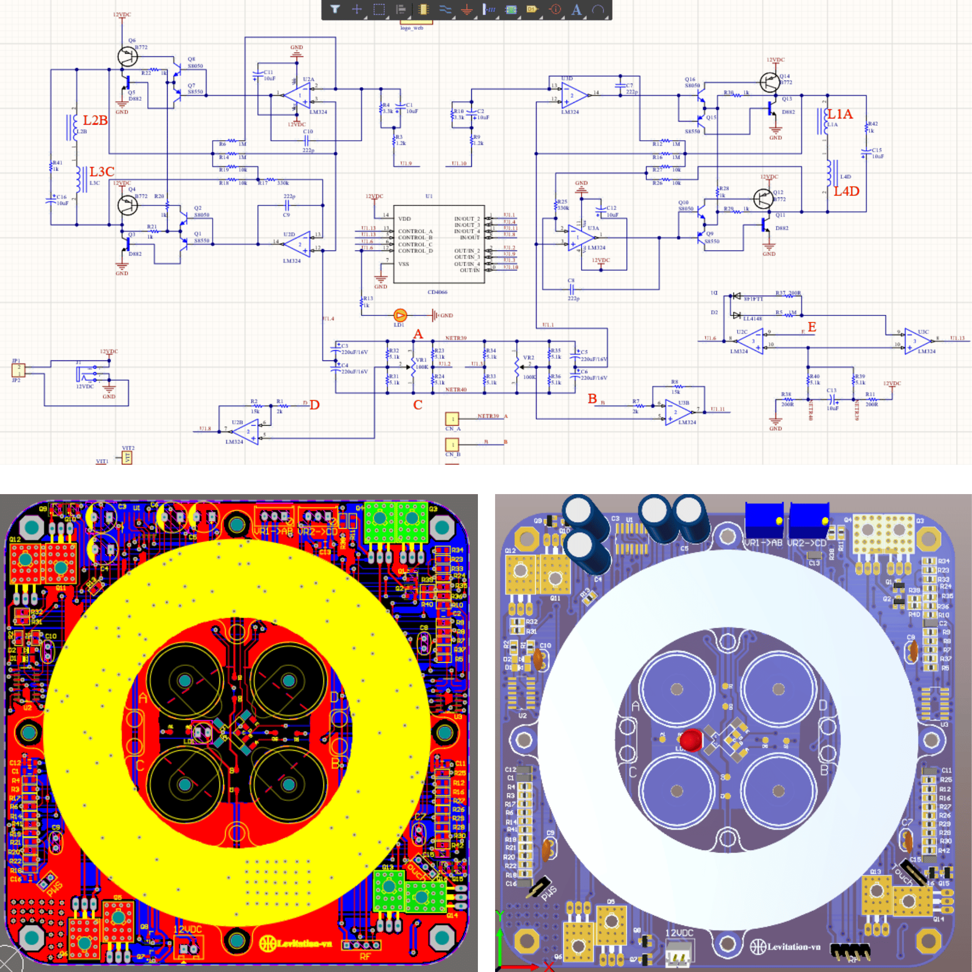
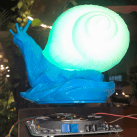
Here is the main circuit diagram of the Magnetic Levitation Base.
":"image="" png","filename":"schematic_layoutpcb_3d_snaillamp_1.png","filesize":908317,"height":1920,"url":"="" assets="" upload="" img="" public="" original="" schematic-layoutpcb-3d-snaillamp-1.png","width":1920}"="" data-trix-attributes="{" presentation":"gallery"}"="">
Here is the main circuit diagram of the Magnetic Levitation Base.
It uses magnetic effects (resonance, magnetic energy compensation) to balance and levitate an object with a magnet.
The circuit diagram, PCB layout (Designed on Altium software), and component list are attached in the link below.
Source Magnetic Levitation Base
Step 3: Magnetic Field Sensor
":"image="" png","filename":"attitudesensorn.png","filesize":293476,"height":720,"url":"="" assets="" upload="" img="" public="" original="" attitudesensorn.png","width":1280}"="" data-trix-attributes="{" presentation":"gallery"}"="">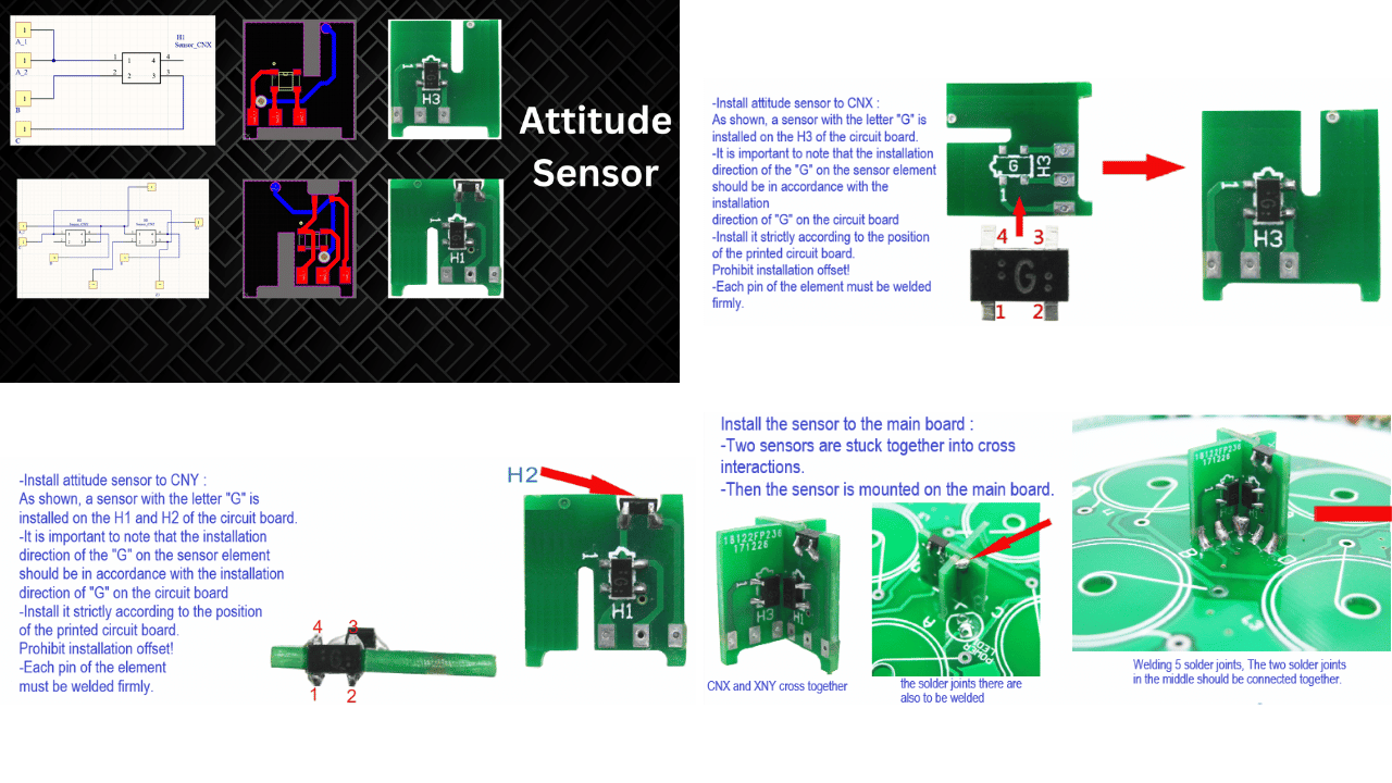
This is the magnetic field sensor,
Step 3: Magnetic Field Sensor
":"image="" png","filename":"attitudesensorn.png","filesize":293476,"height":720,"url":"="" assets="" upload="" img="" public="" original="" attitudesensorn.png","width":1280}"="" data-trix-attributes="{" presentation":"gallery"}"="">
This is the magnetic field sensor,
which helps balance the system based on the magnetic field values.
The detailed soldering method for the sensor is described as shown in the image above.
Source magnetic field sensor
Step 4: Install Inductor
":"image="" png","filename":"install="" inductor="" new.png","filesize":599909,"height":394,"url":"="" assets="" upload="" img="" public="" original="" install-inductor-new.png","width":1271}"="" data-trix-attributes="{" presentation":"gallery"}"="">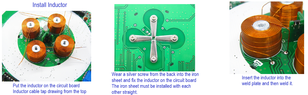 This is the position and soldering method for the coils providing the magnetic field for the main circuit.
Step 4: Install Inductor
":"image="" png","filename":"install="" inductor="" new.png","filesize":599909,"height":394,"url":"="" assets="" upload="" img="" public="" original="" install-inductor-new.png","width":1271}"="" data-trix-attributes="{" presentation":"gallery"}"="">
This is the position and soldering method for the coils providing the magnetic field for the main circuit.Step 5: Attach Special Components to the Main Board
":"image="" png","filename":"c2.png","filesize":713179,"height":439,"url":"="" assets="" upload="" img="" public="" original="" c2.png","width":985}"="" data-trix-attributes="{" presentation":"gallery"}"="">
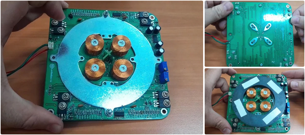
Here is an image of the main board after the electronic components have been assembled and soldered onto the PCB.
You can also see the silver screw from the back into the iron sheet.
fixing the inductor on the circuit board.
A metal iron sheet has been attached to help secure the round magnet of the board.
we will attach the round magnet to the metal sheet on the main board.
This magnet provides the primary magnetic force, which, combined with the automatically adjusted magnetic forces from the four coils, helps balance our Magnetic Levitation Base system.
Step 6: Wireless Power Supply Circuit
":"image="" png","filename":"wireless="" power="" supply.png","filesize":1177784,"height":1080,"url":"="" assets="" upload="" img="" public="" original="" wireless-power-supply.png","width":1920}"="" data-trix-attributes="{" presentation":"gallery"}"="">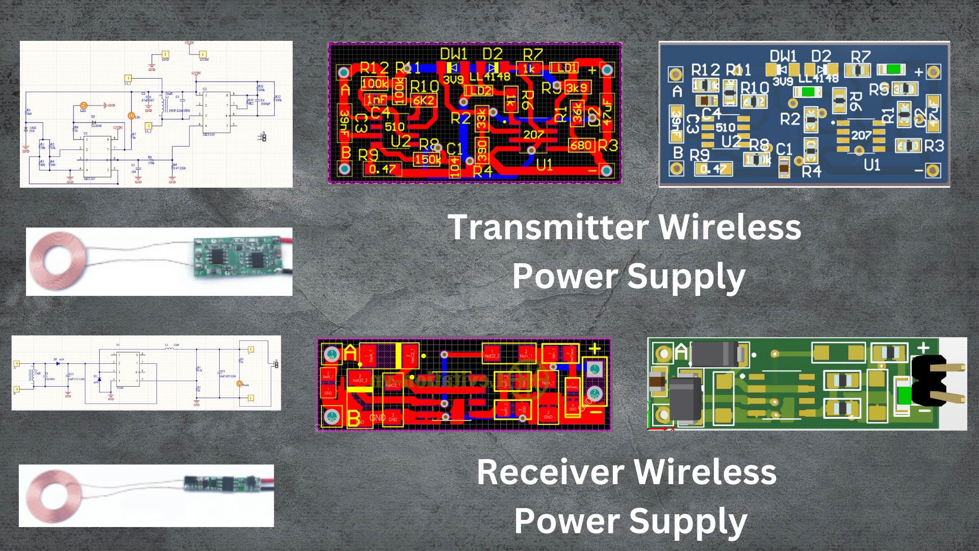
Next is the wireless power supply circuit.
I have also attached the complete circuit diagram, PCB layout (Designed on Altium software), and component list are attached in the link below.
Source Wireless Power Supply
Step 7: Module Led
":"image="" jpeg","filename":"c3.jpg","filesize":77000,"height":457,"url":"="" assets="" upload="" img="" public="" original="" c3.jpg","width":984}"="" data-trix-attributes="{" presentation":"gallery"}"="">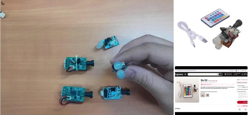
This is the LED module used, which is a 16-color module controlled remotely via a remote control with a rechargeable battery.
Additionally, you can choose different types of LED modules, as they come in a wide variety of qualities, designs, and colors, like some of the modules I have here.
Remember to choose an LED module with a built-in rechargeable battery.
Step 8: 3D Printing Snail Lamp
":"image="" png","filename":"c4.png","filesize":520569,"height":452,"url":"="" assets="" upload="" img="" public="" original="" c4.png","width":979}"="" data-trix-attributes="{" presentation":"gallery"}"="">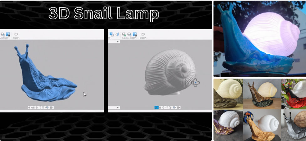
I have also provided you with the design file of the snail lamp so you can 3D print it.
":"image="" png","filename":"c4.png","filesize":520569,"height":452,"url":"="" assets="" upload="" img="" public="" original="" c4.png","width":979}"="" data-trix-attributes="{" presentation":"gallery"}"="">
I have also provided you with the design file of the snail lamp so you can 3D print it.
Based on the file I sent, you can also customize the shape, size, and choose to print it in your favorite color.
Actual image of the snail lamp model after 3D printing.
Here are some beautiful color combinations for the snail lamp that you can refer to.
Source Snail Lamp 3D
Step 9: Solder the Coil Wireless Power Supply
":"image="" png","filename":"c5.png","filesize":508517,"height":491,"url":"="" assets="" upload="" img="" public="" original="" c5.png","width":982}"="" data-trix-attributes="{" presentation":"gallery"}"="">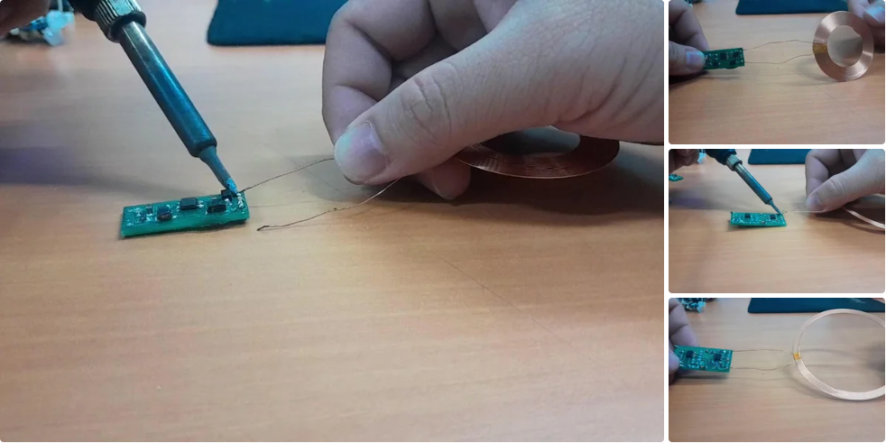
Solder the coil to the receiving board of the wireless power supply.
Solder the coil to the transmitting board of the wireless power supply.
Step 10: Secure the Coil to the Main Board
":"image="" png","filename":"c6.png","filesize":724983,"height":551,"url":"="" assets="" upload="" img="" public="" original="" c6.png","width":982}"="" data-trix-attributes="{" presentation":"gallery"}"="">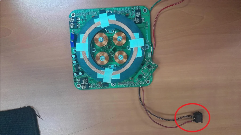
Next, you need to solder the wireless power supply transmitter board and secure the coil to the main board as shown in the image above.
Additionally, you should use a power switch for the transmitter board to enable you to control the charging mode for the Snail Lamp.
Step 11: Testing the Wireless Power Supply
":"image="" jpeg","filename":"20240729_184607="" -="" frame="" at="" 0m5s.jpg","filesize":109243,"height":800,"url":"="" assets="" upload="" img="" public="" original="" 20240729-184607-frame-at-0m5s.jpg","width":720}"="" data-trix-attributes="{" presentation":"gallery"}"="">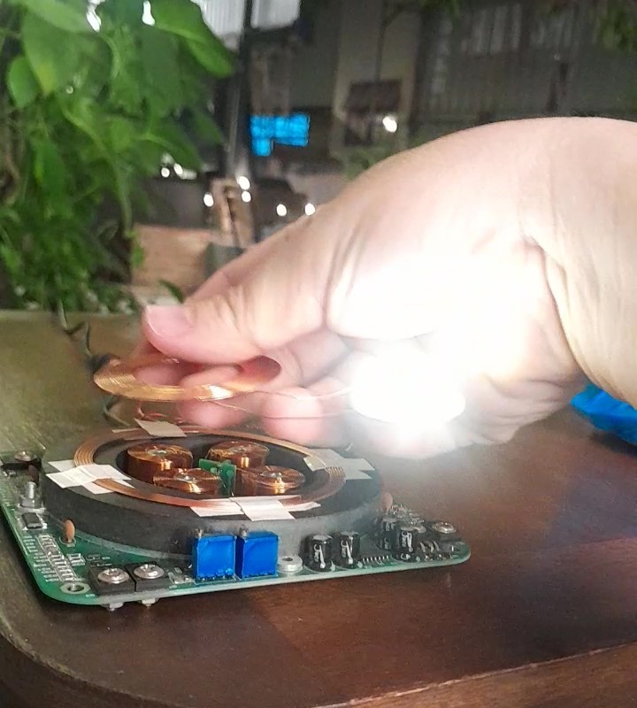
I am testing the wireless power supply transmitter board's ability to provide remote power.
A small note for you: the charging distance, whether near or far, depends on the type of coil you choose for the transmitter/receiver wireless power supply circuit.
In other words, the inductance value of the coil affects the distance at which the circuit can supply voltage.
Step 12: Attach Led Module and Components to Snail Lamp
":"image="" png","filename":"coverhackover2.png","filesize":508768,"height":480,"url":"="" assets="" upload="" img="" public="" original="" coverhackover2.png","width":944}"="" data-trix-attributes="{" presentation":"gallery"}"="">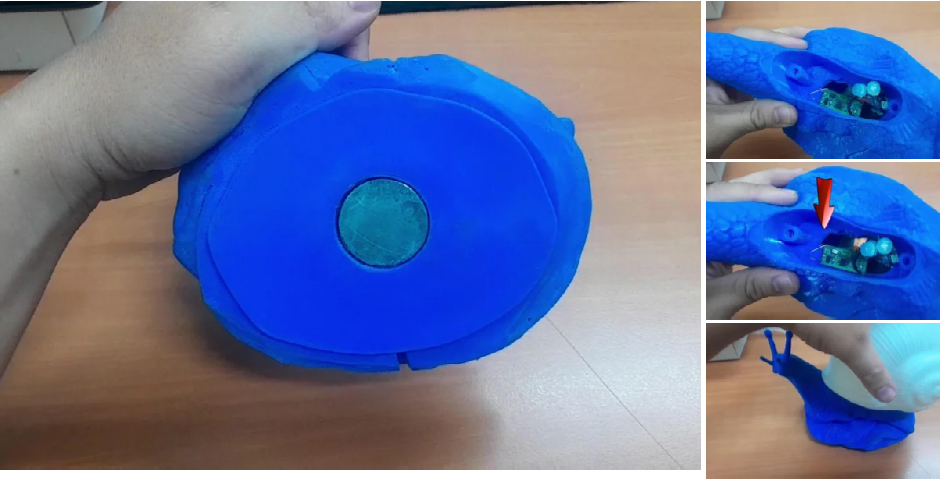
Attach the magnet to the base plate of the snail lamp with glue.
":"image="" png","filename":"coverhackover2.png","filesize":508768,"height":480,"url":"="" assets="" upload="" img="" public="" original="" coverhackover2.png","width":944}"="" data-trix-attributes="{" presentation":"gallery"}"="">
Attach the magnet to the base plate of the snail lamp with glue.
You can see in the Image that I have attached the receiving board of the wireless power supply module and the led module to the inside of the snail lamp and they are attached with glue.
An important note is the receiver coil of the wireless power supply circuit should not be placed directly at the center of the magnet because the magnetic field of the magnet will affect the charging capability of the circuit.
You can place it above the lamp instead.
The last job is to attach the snail shell to its body to complete this interesting Snail Lamp.
Step 13: Check the Functionality of Magnetic Levitation Base
":"image="" jpeg","filename":"20240729_184510.jpg","filesize":117998,"height":801,"url":"="" assets="" upload="" img="" public="" original="" 20240729-184510.jpg","width":800}"="" data-trix-attributes="{" presentation":"gallery"}"="">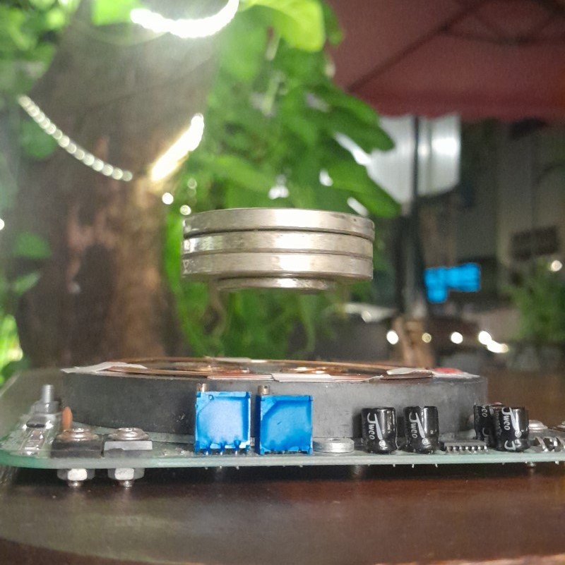
":"image="" png","filename":"suspendedmatter.png","filesize":2653009,"height":1080,"url":"="" assets="" upload="" img="" public="" original="" suspendedmatter.png","width":1920}"="" data-trix-attributes="{" presentation":"gallery"}"="">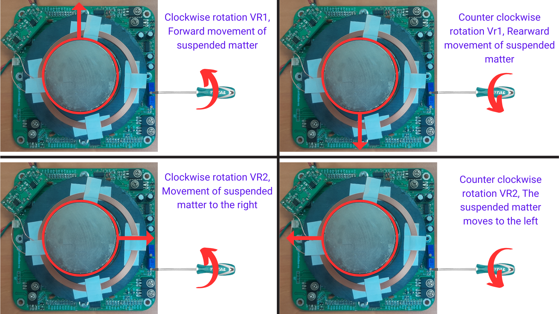
The next step is to check and adjust the magnetic field of the Magnetic Levitation Base so the snail lamp can float in the air.
Use a 12V adapter to power the board.
Slowly move the magnet from top to bottom, if the magnet can balance and float, you can skip adjusting VR1 and VR2.
If the magnet cannot be hung, it is necessary to adjust VR1 and Vr2. The adjustment method is as above.
Please subscribe to the channel so you don't miss the upcoming interesting DIY product guides and help motivate me to create more videos. Thank you!
Please subscribe to the channel so you don't miss the upcoming interesting DIY product guides and help motivate me to create more videos. Thank you!
Discussie (1 opmerking(en))
S.I ,Elektor 3 maanden geleden
First of all, let me say that this is an excellent project—thank you for sharing it on Elektor Labs! Considering this is your first submission, I’m confident there are many more exciting and innovative projects coming from you in the future. Looking forward to seeing what’s next!