DIY SMARS Robot Version 2.0: Enhanced with new features
Upgrade your SMARS Robot with OLED, RGB LEDs, and a buzzer! Follow my guide for circuit design, 3D printing, and custom Android app control.
Welcome to the second version of the DIY SMARS Robot! In this tutorial, I’ll guide you through producing this enhanced robot with new features like an OLED display, RGB LEDs, and a buzzer for melodies. Follow along as we design the circuit, assemble the PCB, and 3D print the mechanical parts. Let's bring this robot to life with motion control, Bluetooth connectivity, and customizable eye expressions.
Supplies
Electronics Components:
Atmega328p Microcontroller (SMD VQFN version)
L293 Motor Driver (SMD)CH340 IC (USB to TTL converter)
WS2812 RGB LEDs (12 pieces)
Active Buzzer
SIL Headers (for ultrasonic sensor and OLED display)
9V Battery
LM317 Voltage Regulator
Resistors and Capacitors
Diodes and Transistors
Crystal Oscillator (16MHz)
PCB and Soldering:
Custom PCB (ordered from JLCPCB)
Solder Paste
PCB Stencil
Flux Remover Solvent
Hot Plate (or reflow oven)
Mechanical Parts:
3D Printed Parts (STL files available on Thingiverse)
1.6mm Brass Wire (or 1.75mm 3D printer filament for chain joints)
Small DC Motors (2 pieces)
Screws and Nuts (for assembly)
Super Glue
Displays and Sensors:
OLED Display
Ultrasonic Sensor (HC-SR04 or similar)
HC-05 Bluetooth Module
Tools and Software:
3D Printer
Altium Designer (for circuit design)
Arduino IDE
MIT App Inventor
Soldering Iron and Solder
Microscope (for inspecting solder joints)
USB-C Cable (for programming)
Additional Components:
Threaded Inserts (2mm for OLED display housing)
Circuit Schematic And PCB Design
Circuit Schematic Design
Begin by designing the circuit schematic in Altium Designer. The heart of the design is the Atmega328p microcontroller in its SMD VQFN version, chosen for its compact size. Integrate the following components into the schematic:
L293 Motor Driver (SMD): For controlling dual DC motors.
CH340 IC: To convert USB data to TTL, enabling direct programming from the Arduino IDE.
WS2812 RGB LEDs (12 pieces): For colorful light emission.
Active Buzzer: Connected to pin 3 of the microcontroller for melody output.
SIL Headers: For the ultrasonic sensor and OLED display connections.
Miscellaneous Components: Include resistors, capacitors, diodes, transistors, a crystal oscillator (16MHz), and necessary connectors.
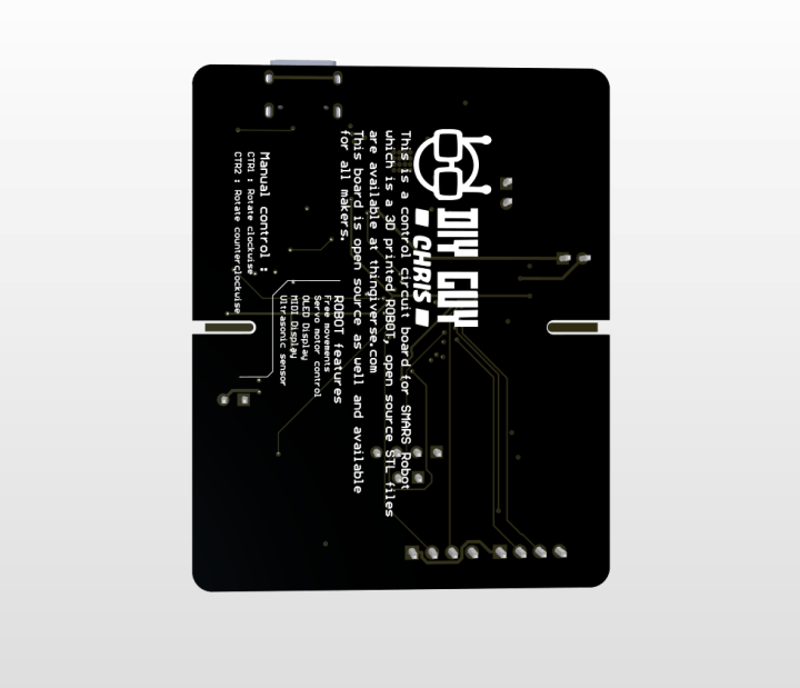
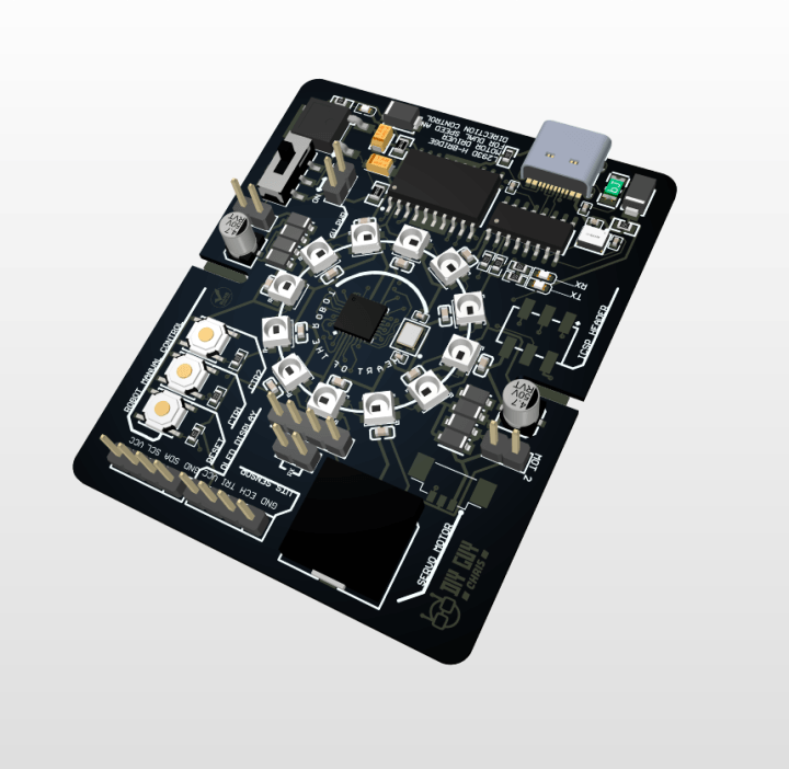
PCB Design and Manufacturing
With the schematic completed, transition to designing the PCB layout. Ensure the PCB dimensions match an Arduino UNO board for compatibility with the robot chassis. Here are key placements:
Right Side: Position the USB connector and CH340 IC.
Left Side: Place the OLED and ultrasonic sensor connectors.
Microcontroller Placement: Centralize the Atmega328p and surround it with the 12 RGB LEDs.
Motor Driver: Ensure the L293 motor driver has a copper area heatsink as recommended in the datasheet.
Generate the GERBER files and order the PCB from a manufacturer like JLCPCB, selecting a black soldermask for a sleek finish. Don't forget to order a PCB stencil to aid in the solder paste application process.
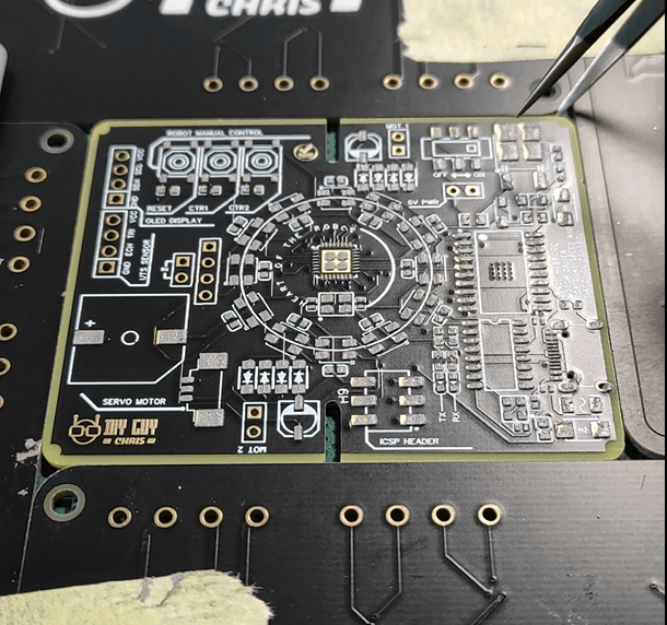
Solder Paste Application And Component Soldering
Solder Paste Application
With your PCB and stencil ready, the next step is to apply the solder paste. Begin by securely positioning the PCB using some old PCBs or a jig to keep it steady. Align the stencil over the top side component pads accurately. Drop the solder paste onto the stencil and gently spread it across the pads using a squeegee or a similar tool. Ensure the paste is evenly applied to all the pads to guarantee a clean and efficient soldering process.
Component Placement
Once the solder paste is applied, start placing the SMD components onto the PCB. Use tweezers to carefully position each component on its corresponding pad, following your design layout. Pay attention to the orientation of components like the LEDs and the ICs to avoid placement errors.
Soldering
After all components are in place, use a hot plate or reflow oven to solder them onto the PCB. If using a hot plate, gently place the PCB on the preheated surface and monitor the soldering process. The solder paste will melt and form solid solder joints. If using a reflow oven, follow the recommended reflow profile for your solder paste.
Inspect the solder joints under a microscope to ensure they are properly formed and there are no solder bridges or cold joints. Clean the board with a flux remover solvent to eliminate any residual flux, resulting in a clean and professional finish.
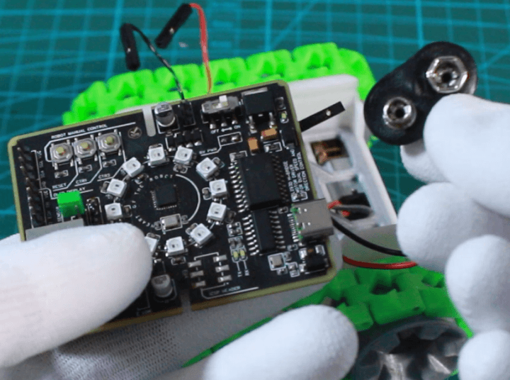
Solder the through-hole connectors for the OLED display, ultrasonic sensor, and motor outputs. Attach the HC-05 Bluetooth module and the 9V battery connector to the PCB. Ensure all connections are secure and test each component for functionality.
Mechanical Parts And OLED Display Assembly Mechanical Parts Assembly
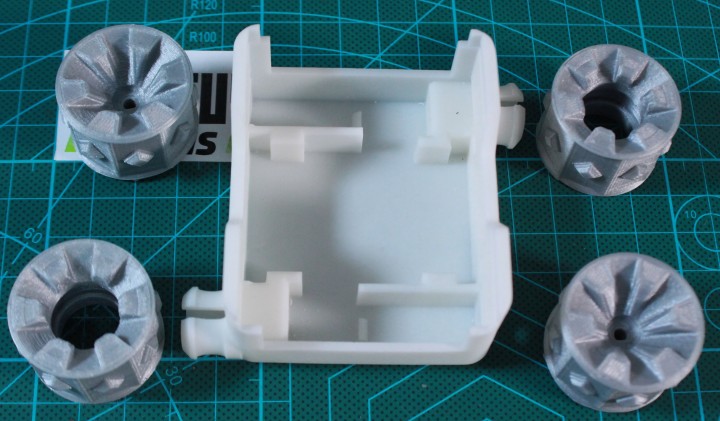
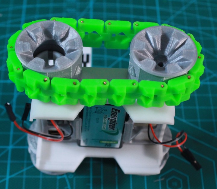
Begin by 3D printing the mechanical parts of the robot using the STL files available on Thingiverse. Once printed, assemble the robot chains. You can use 1.6mm brass wire or 1.75mm 3D printer filament for the joints. Insert the wire or filament through the links to create flexible chains. Secure the joints with super glue if needed. You'll need 16 pieces per chain, making a total of 32 pieces for both chains.
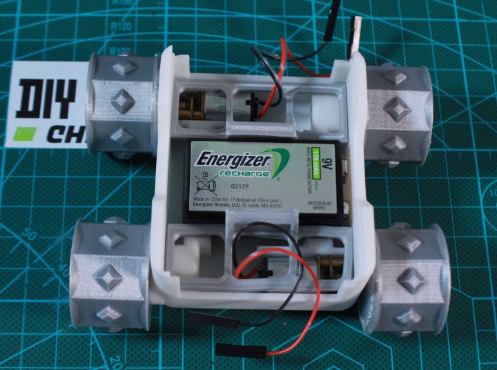
Next, attach the wheels to the DC motors. Start with the slave wheels, applying some force to fit them in place. Then connect the master wheels to the small DC motors. Secure the DC motors and the 9V battery in their respective holding board parts. Finally, attach the chains to join each slave wheel to its master wheel, completing the mechanical assembly of the robot.
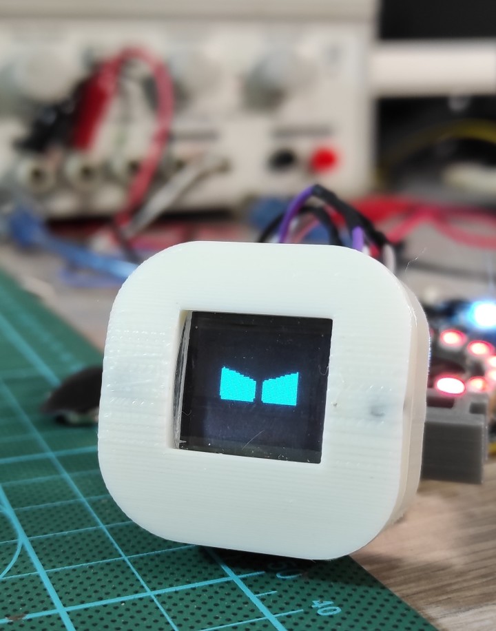
OLED Display Housing Assembly
For the OLED display, design and 3D print a housing. Insert 2mm threaded inserts into the housing to provide secure mounting points. Place the OLED display into the housing and secure it with screws. To enhance the display clarity, consider adding a resin cover to the housing. Screw the housing cover in place to complete the assembly.
Now, you have both the mechanical parts and the OLED display housing ready for integration with the PCB.
Android App Development
Developing the Android App
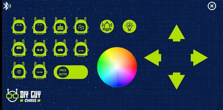
To control your SMARS Robot, you will need a custom Android app. Using MIT App Inventor, develop an app that includes:
Directional Controls: Buttons for forward, backward, left, and right movement.
LED Control: A color wheel to manually control the RGB LED light colors.
Expressions: A set of eyes expressions to display different emotions on the OLED screen.
Set up the app to transmit serial characters over Bluetooth for each button press. Here’s a brief overview of the steps:
Create a New Project: Open MIT App Inventor and start a new project.
Design the Interface: Add buttons for movement, a color wheel for LED control, and image assets for eye expressions.
Set Up Bluetooth Communication: Integrate Bluetooth connectivity to send serial data to the robot.
Assign Actions to Buttons: Configure each button to send specific serial characters to control the robot’s movements, LED colors, and expressions.
Coding for the Robot
Develop an Arduino code to interpret the serial characters sent from the app. This code should:
Control Motor Movements: Based on directional commands.
Change LED Colors: According to the color wheel input.
Display Eye Expressions: On the OLED screen as per the selected emotion.
Upload the code to the Atmega328p microcontroller using the Arduino IDE. Before uploading, un-bridge the Bluetooth RX line. After uploading, place back the jumper to re-establish the Bluetooth connection.
Now, you’re ready to test your Android app with the assembled SMARS Robot.
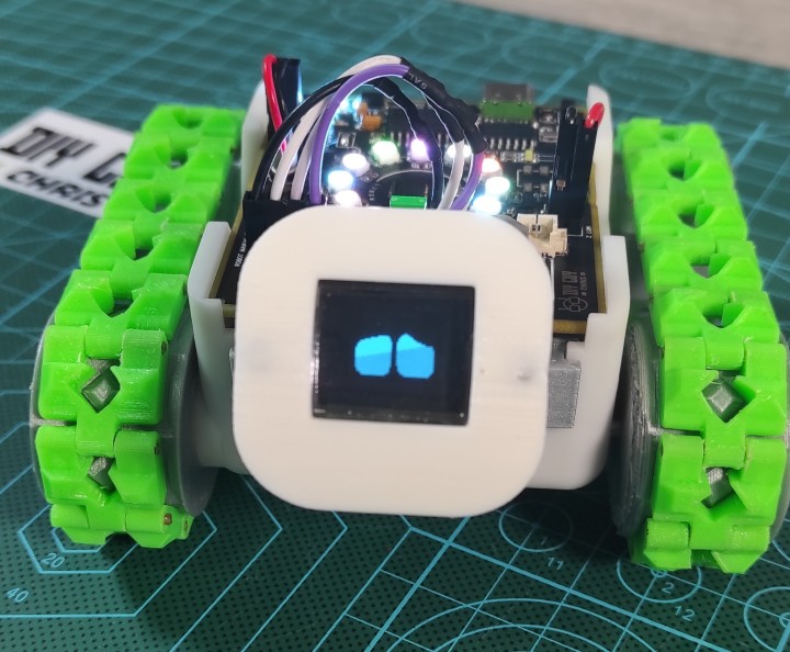
Final Assembly And Testing
Connect the circuit board to the 9V battery and insert it into the robot chassis. Connect the motors and OLED display to their respective connectors. Upload the Arduino code, ensuring to un-bridge the Bluetooth RX line during programming. Test the robot using the custom Android app developed in MIT App Inventor, verifying all functionalities including motion control, LED color changes, and eye expressions.
Conclusion
Congratulations! You have successfully built the second version of the DIY SMARS Robot. Enjoy exploring its new features and feel free to share your own modifications and improvements. Keep creating and happy making!


Discussie (0 opmerking(en))