High Precision Isolated Voltage and Current Monitor with HX711 24 bit ADC


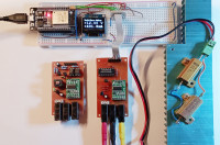
The goal of this project is to develop a highly accurate current-voltage monitor that only costs a few euros and should also be universally applicable.
To ensure that the circuit can be used universally, the power and data transmission were isolated. There are many reasons to isolate circuits, most notably to avoid ground loops, eliminate conducted noise in electronic circuits and protect from high volt voltage areas. There is no common mode error also on high-side current sensing. The ADC HX711 offers the advantage that no data input signal is necessary. This simplifies the interface, but despite this it is possible to select the input channel and gain.
Variant 1:
Isolate power supply with transformer and data/clock transmission with optocoupler
The advantage: coupling with low capacitance (several picofarad), the best choice for high voltage, such as mains voltage.
Variant 1:
Isolate power supply with transformer and data/clock transmission with optocoupler
The advantage: coupling with low capacitance (several picofarad), the best choice for high voltage, such as mains voltage.
Variant 2:
Isolate power and data transmission with capacitors
Advantage: no special components necessary like optocoupler and transformer.
Suitable for low voltages up to 40V. There are high voltage capacitors available, but if there occur transients (e.g. switching off and on), the circuit can be damaged because of the high coupling capacitance (about 100nF).
A full description can be found in the Attached pdf.


Discussie (5 opmerking(en))
Martin Schönegg 7 maanden geleden
2nd hint:
24 Bit only means the resolution but not the accuracy. There is no valuable reference voltage on these HX711 boards. It is designed only for relative measurements of two resistances / bridge sensors like scales and preassure.
hx711-modified-version.JPG (94kb)
jost 7 maanden geleden
It is true that the 24 bits only refer to the resolution and not to the accuracy. This was also mentioned in the description. Even the resolution is only a theoretical value, because the noise level is higher than one LSB. The device has a band-gap reference voltage (1.2V), which is not absolutely necessary for resistance bridges. Approximate measurement showed a temperature coefficient of approx. 25uV/degreesC or 20ppm/degreesC. A precision voltage reference like ADR293 shows a temperature coefficient of 10 to 30 ppm/degrees C depending of grade.
Martin Schönegg 7 maanden geleden
2. The 27 k Resistor is parallel to R1 leading to an effective resistance of 11.48 k. This should result in 3 V AVDD. My guess is, that the original intention was to establish 3V as VDD, because ESPxy, RasPi pico or STM32 uses 3V3 as VCC. For using such µCs these 4V3 is useless. 4V3 is a strange value but explainable with the assumed error using Vbg * (R1/R2) instead of the correct formula, this calculation would lead to the values seen with the goal of 3 V (Ok, 2V9 ;-). I guess, a chinese trainee made this error and all copied this without prooving.
Vbg is 1.25 V not 1.2 V in the datasheet, I have (AVIA Semiconductor which is yours, I don't have seen information about stability of Vbg).
The useless voltage regulator (DVDD = 3V3 with AVDD set to 4V3) increases noise instead of stabilasing and smoothing AVDD. For absolute measurements, it is even more important to have a stable and low noise AVDD.
3. Seems like you have a better layout. It looks good and may be the backside of your PCB is a ground plane. Where did you buy these?
4. Be careful, the values are internal smoothed by a moving average with 4 values. With 10 Hz sample rate, the true value is given after 400 ms!
Regards
Martin
jost 6 maanden geleden
1. You are an experienced user of this module. I found several threads that address this problem.
My module has a correct GND connection and a ground plane. Lucky! See attachment.
2. Because of the isolated circuit, the ADC can also be operated with higher voltage (5V) in connection with ESP32, then the LDO does what it should do. I found another formula in AVIA Semiconductor datasheet which is also wrong Vavdd=Vbg*(R1+R2)/R1 (R1=20k, R2=8.2k, Fig. 1 datasheet, voltage at R2 = Vbg) should be Vavdd=Vbg*(R1+R2)/R2 and short form Avdd=Vbg*(1+R1/R2). The measured Vbg voltage on my modules is 1.2V and not 1.25V as in the specification. I estimated the stability by heating the module to 100degC and calculated the coefficient. I agree that a stable and low-noise Avdd is important.
3. In my two circuit variants AVdd and E- are also connected again. I bought the modules on Amazon, but currently not available: https://www.amazon.de/dp/B07GT2HYFJ?ref=ppx_yo2ov_dt_b_fed_asin_title
Other supplier: https://de.aliexpress.com/i/1005002997265844.html
4. Thanks for the tip, but it is not visible on the display.
Thanks
Johannes
FredVictor 7 maanden geleden
Any chance of a rough BOM to help with sourcing the more unusal parts which will fit your boards ?
TIA
jost 7 maanden geleden
FredVictor 6 maanden geleden
Charles Danis 9 maanden geleden
Great thanks
Regards
jost 9 maanden geleden
Charles Danis 9 maanden geleden
Nice project , does gerbers files will be available ?
Regards