

IV-3 VFD shield for Arduino
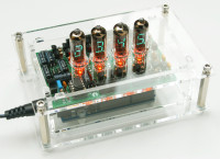
This Arduino shield is capable of driving 4 Russian IV-3 7 segment VFD tubes. 4 3mm LEDs provide background lighting for the tubes.The design is completely based on through hole components, no SMD components were used. As such, the PCB can easily be assembled by anyone who has some soldering experience. Also, the components used are cheap and easily available.
This Arduino shield is capable of driving 4 Russian IV-3 7 segment VFD tubes. 4 3mm LEDs provide background lighting for the tubes.
The design is completely based on through hole components, no SMD components were used. As such, the PCB can easily be assembled by anyone who has some soldering experience. Also, the components used are cheap and easily available.
As this was designed as a more educational, easy to build project based on easily available components it is not the best possible solution to drive these VFD tubes from a technical point of view.
Video: https://vimeo.com/90783398
Buy the kit at: http://www.elektor.nl/iv-3-vfd-shield-for-arduino-kit-150064-71
Buy the case at: http://www.elektor.com/plexiglas-housing-for-iv-3-vfd-shield-for-arduino
Discussie (1 opmerking(en))
kh.ziener 9 jaar geleden
Habe das Shild in Bascom programmiert. Es ist eine DCF77 Uhr geworden. Das DCF-Modul erhält seine Versorgungsspannung an PortB.4 (12) und das Signal wird an PortB.3 (11) angelegt. Natürlich kann man das Modul an 5V anlegen, was aber die Sicht auf die Anzeige beeinträchtigt.
HaSch 4 jaar geleden
Hans
Edit: Meanwhile, I dimmed the LEDs not via analog.Write() but using Timer2 and writing some new code. It works very well. I merged with thermometer, also. So the sketch can display real time without the need of setting the clock every time when power was off, date and temperature (with LEDs dimmed as real valves!). Time is displayed every minute from second 55 to 44, date from 45 to 49 and temperature from 50 to 54.
Kevin Smith 4 jaar geleden
HaSch 4 jaar geleden
attached you find my combined code for displaying time (with RTC) and temperature (sensor DS18S20, DS1822 or DS18B20). As RTC I didn't use the DS1307 anymore as it is not very accurate and needs to be adjusted after a short time. I use ChronoDot (Adafruit) as it's a temperature compensated DS3231SN chip. Once set it can be forgotten. You also can order a cheap China clone. ChronoDot needs to be connected to I2C interface of Arduino Uno, also to pins 5V and GND. You can find all wiring in the sketch. The temperature sensor probably needs to be calibrated to show the correct room temperature, I added a constant to make it work.
With my code it is even possible to dim the red LEDs to make it look as a real valve heating. Very nice!
Have fun!
Hans
Kevin Smith 4 jaar geleden
HaSch 4 jaar geleden
Kevin Smith 4 jaar geleden
Thanks for your help and understanding.
HaSch 9 jaar geleden
bera 9 jaar geleden
PPihkala 9 jaar geleden
HaSch 9 jaar geleden