

Magnetometer with home-made sensors
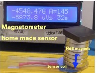
A magnetometer that is suitable to measure fields from earth-fleld up to many Tesla using the very direct flux integration technique is presented. For home use it is especially useful to measure the fields of strong permanet magnet arrangements. As sensor, home-made little probe coils are used that can be made suitable to the measurement problem. In principle the calibration to absolute values just requires knowledge of the probe coil geometry.
Looking for a means to measure the magnetic field of single and arrangements of NbB magnets I remembered a kind of “archaic” method. I.e. the integration of the voltage pulse that is induced when a probe coil is placed int the unknown field. In the old days such measurements were performed by (astonishingly sensitive, i.e. a few microVs) “ballistic” or “creep” galvanometers (see for example the book “Elektrizitätslehre” by R.W. Pohl chapters VI to IX, Springer-Verlag, Berlin-Heidelberg-NewYork 1967; the first edition was from 1927). So, my challenge was to try to realize such a measurement using more modern electronic means, namely an operation amplifier based integrator.
For the hobbyist the advantage of this method is the possibility to home-make the required sensors (sensor coils) to cover ranges from a few Gauss (earth field strength is about 0.5 Gauss) up to several Tesla (1 Tesla = 10000 Gauss). Where 1-2 T is probably the ultimate field strength that can be encountered at home. While the few Gauss range nowadays is usually available in smart phones and uncalibrated cheap Hall sensors extend to a few 100 Gauss, typically further extending the range requires more professional (expensive) equipment.
If a conductor is moved within a magnetic field (and “crosses” magnetic field lines) a voltage is induced. This is used in devices from electric generators to dynamic microphones. In particular if a close conductor loop spanning an area A is transferred from a zone without field into a region with field B a voltage pulse U(t) is induced an may be measured. Before start and after finishing the transfer, the voltage is zero but during the transfer nonzero readings with an arbitrary time function is observed. The key point is that the integral over U(t) is B times A , i.e. one may measure B by dividng the voltage intergal bs the prrobe coil area A.
The main challenge of the presented method pertains the tiny voltages involved. As example we may consider a moderate probe coil with 500 turns of 1 cm^2 , i.e. A=0.05m^2 and a moderate field of 100 Gauss = 0.01 Tesla = 0.01 Vs/m^2 (200 times the earth field). In that case we expect a pulse with an integral of 0.5mVs. If we now want that we have 100sec to read off the result wit 1% accuracy the allow offset voltage to the integrator is only 50nV! This is lower than typical thermovoltages and op-amp offsets. The present magentometer setup is a test how far the control of offset can be driven with moderate effort to achive a decent magentometer operation.
Further aspects of integration capacitor selection and calibration issues are addressed in the attached full description.
Discussie (0 opmerking(en))