

Nixie bargraph thermometer with Arduino
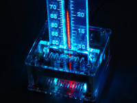
This USB powered thermometer based on an Arduino Nano shows the temperature using a vintage Russian "nixie" style IN-9 bargraph tube.
Besides the well known numerical nixie tubes, other types of neon filled tubes were also used in the past for specific applications. For linear gauge displays, neon filled bargraph tubes were used. The most prevalent types of these tubes are the Russian IN-9 and IN-13 linear indicators. These tubes are technically not nixie tubes as they do not show digits but they were used during the same time period and they share the same warm vintage look.
Most of the "nixie" thermometer kits on the market are based on the IN-13 bargraph tube. Compared to the IN-13 tube, the IN-9 is quite unpopular as many people run into problems when they try to use them in their projects. An IN-9 tube consists of a nickel plated anode mesh and cathode of molybdenum wire. Due to the use of molybdenum, the ignition voltage of the neon gas mixture in the tube remains quite low (< 140 V). At the bottom the molybdenum wire is coated with zirconium which has an even lower ignition voltage. As a result the bargraph column tends to start at the bottom.
Opposed to the IN-9 tube, the IN-13 tube uses an auxiliary cathode to make sure the glow starts at the bottom. As IN-13 tube stocks become more and more depleted we had no other option than to use the IN-9 tube.
The two main problems with this tube are the bargraph display not starting at the bottom (column breaks) and cathode poisoning where the bargraph display cannot reach the end of the tube. The cathode poisoning problem can in most cases be solved by a burn-in procedure where the tube is subjected to overcurrent until the glow reaches the end of the tube. The other issue is a lot more trickier...
Originally, IN-9 tubes were used for indicating mains voltages and currents or similar voltages and were often driven with half-wave rectified current instead of DC. There was a discussion about this on the NeoNixie newsgroup and there was even a schematic posted by user "Start End". The trick is to switch the tube on and off around 50 - 100 times per second. We did a lot of tests with this setup and it works remarkably well. The only drawback is that the linearity is not very good, but that can easily be corrected in software.
The complete thermometer circuit consists of a 5 V to 150 V "voltage doubler" step-up converter, an IN-9 tube driver based on a low voltage rail-to-rail opamp, two RGB leds and an Arduino Nano. We did choose a very cheap Chinese Arduino Nano clone. As such, there are no SMD parts to solder and for the price of the Arduino Nano we couldn't even supply a partially pre-assembled PCB with a microcontroller and a USB to serial converter IC.
The Arduino Nano switches the IN-9 tube on and off around 75 times a second, so the display does not show any flickering. To prevent cathode poisoning of the IN-9 tube, a sweep animation is displayed at an adjustable interval. The temperature sensor is a DS18B20. As the total power consumption is less than 1 W, the thermometer can even be powered via a standard USB port on a computer.
Discussie (5 opmerking(en))
Skalolaz 4 jaar geleden
Yuri Vorobets 4 jaar geleden
OliX 4 jaar geleden
I have one completely fine functioning thermometer with the included sensor.
Now I am on my second one which works fine hardwarewise with the included one wire sensor but I wanted to use it as hygrometer. As sensor I bought a DHT22 which also works on it's on own when I let it show it's measurements on the serial monitor. Therefore I can say both, the sensor and the thermometer works well.
But I don't get the Arduino sketch adapted to read from DHT22 and show the values on the IN-9 tube. What do I have to change use most of the code for controlling the device but instead of the DS1822 sensor using the data from DHT22.
Thanks a lot in advance and best regards
Axiris 4 jaar geleden
I advice you to study the sketch to understand how the program works. There are more than a dozen tasks (the _Exec() functions) that comprise the functionality of the thermometer, you should understand what each task does and how they cooperate. The debug defines are also very useful for controlling the amount of debug-prints.
Since you want to replace the 1-Wire sensor with a DHT22, you can remove the tasks and related code you won't be needing, like the code for 1-Wire. After that, you can add one or more tasks for reading your DHT22 and displaying the values on the tube in whichever fashion you've in mind. The Tube_Ctrl_Set_Value() function is worth noting here, it sets the PWM value of the IN-9 tube.
Changing an existing program of this magnitude may be tedious. Altenatively, you could create a sketch from scratch.
Good luck.
Mras2an 5 jaar geleden
Please, can you tell me what is the goal of the IC2B?
Tkx.
Axiris 5 jaar geleden
When using an USB cable between the USB power adapter and the thermometer, there will also be a voltage drop due to the resistance of the wires in the USB cable when the thermometer draws current.
The Arduino Nano has an on board voltage regulator which provides a stabilized 3.3 V which I use to drive the tube via the 2N7000 mosfet transistor. As such, the exact USB power adapter voltage and a possible voltage drop over the cable do not affect the display height on the IN-9 tube.
If you choose to use the 5 V supply, you can connect the D5 output on the Arduino directly to R18 (without mounting T4 and R12) but I would not recommend this unless you have a very stable 5 V supply.
Mras2an 5 jaar geleden
thank you
Axiris 5 jaar geleden
IC2B is not used and has no function in the circuit. However, an unused op amp needs to be terminated properly. That's the reason we used 2 10K resistors.
More information about terminating unused op amps can be found here:
http://www.ti.com/lit/an/sboa204a/sboa204a.pdf
jerome 6 jaar geleden
Savez vous d'où peut venir ce sautillement du tube?
Merci
jerome 6 jaar geleden
@F1Andy:
A la première mise en service, je n'obtenais que 130v en tournant P1.
Maintenant, après que le thermomètre ait fonctionné ( tous le composants ont atteind leur températures, sur vos conseils, j'ai effectué une autre mesure, j'obtiens 170v.
J'ai donc ajusté à nouveau P1, pour obtenir 150V.
Maintenant plus de scintillement.
@Axiris:
Le problème venait d'un mauvais réglage de P1
Merci beaucoup, le problème est réglé.
Axiris 6 jaar geleden
If the problem persists after running the thermometer for a few days, you can ask the Elektor customer service for a replacement tube.
F1Andy 6 jaar geleden
Also check the PWM signal from the Arduino is steady.
Andy
F1Andy 6 jaar geleden
I understand cathode poisoning occurs in thermionic tubes where material emitted from the heated cathode does not get pulled away by the charge on the anode, and fall back to the cathode surface. Hence it is not a good idea to run a tube with heaters on and no HT for extended periods of time. (There are of course exceptions, and I may not understand this correctly)
But these are cold tubes, without heaters. So what is the cathode in a nixie being poioned with, and how does randomly turning on more segments of the bargraph stop it? Surely that would just poison the other segments too?
Thanks
Andy
Axiris 5 jaar geleden
It is normal for the anode voltage to drop under a heavy load like a tube burn-in procedure. You can try to burn-in the tube using a more powerful high voltage supply if you have one.
You can also ask Elektor for a replacement tube. After all it is old technology and some tubes may have problems despite the fact that we test them before shipping them with the kits.
Kind regards,
Ilse Joostens
netzwerk-manne 5 jaar geleden
ich habe gerade den Komplettbausatz von Elektror bekommen und zusammengebaut. Ich habe die Anodnspannung auf 150V eingestellt, dann stromlos gemacht, den Jumper auf 2-3 für den Burn-In gesteckt. Dann wieder eingeschaltet.
Angangs leuchtete die IN-9 von unten an bis ca. 25 ° C. Jetzt, nach ca. 60 Minuten stehr sie immer noch bei 29 ° C! Das das Maximum ca. 12mm von dem oberen, weißen Strich sein soll, mag ja sein, aber da komme ich nicht hin. Es bleibt bei 29 ° C stehen.
Ich habe noch einmal die Spannungen kontrolliert, die passen. In Stellung 2-3 beträgt die Anodenspannung derzeit 107 Volt.
Kann mir bitte jemand einen Tipp geben, was das sein kann?
Beste Grüße
Manfred Köhler
Axiris 5 jaar geleden
Settings message: Did you write the settings to EEPROM? Use command "settings write" or its short form "s w".
Compiler warning: it's about syntax, just ignore it.
Yuri Vorobets 5 jaar geleden
Yuri Vorobets 5 jaar geleden
After I downloaded the program to Arduino, the Serial Monitor displays a message: "Settings: settings are undefined or invalid"
When I load the program into Arduino using the programmer, the result is the same. Help me please.
Skalolaz 3 jaar geleden
Yuri Vorobets 3 jaar geleden
Ввиду отсутствия чертежей корпуса, этот термометр так и не доделал...
Skalolaz 3 jaar geleden
Yuri Vorobets 3 jaar geleden
Joachim Ballandat 5 jaar geleden
the Tube cannot be defect if showing the maximum. I suppose, that T4 (2N7000) is defect. Can you measure the PWM-Signal at the Gate and at the Drain ?
Best regards, Joachim Ballandat
Kristian Bakker 5 jaar geleden
can anybody help me with problem on the nixie tube. My tube is constantly showing the maximum pwm value. I feel like i've tried everything and I hope there is a solution. All the components are on the right spot and when I measure de whole circuit I don't find anything wierd. In Arduino IDE the temperature Sensor is present and giving the right degrees. My RGB lighting is also working fine. I filled in the whole conversion Table and all the settings are correct. I also replaced the MPSA42 transistors because I thought that was the problem. This did not change a thing. The tube just can't be driven, also not manualy. I acctualy bought 2 kits and I tried replacing a lot of components like IC1 and IC2. nothing seems to work. Because everything seems to be right I now start to think that the tube is defect allthough it is showing at max height.
I was wondering is this is a known problem and I hope anyone can help me.
Regards, Kristian Bakker
Martin Grothe 6 jaar geleden
heute Mittag konnte ich am Thermometer weiter basteln und jetzt läuft es.
Nachdem ich am Pin3 vom Operationsverstärker nur Milivolt messen konnte,
lag die Vermutung das der MOSFET T4 defekt ist nahe. Getauscht und läuft.
Danke für die Tips.
Joachim Ballandat 6 jaar geleden
Axiris 6 jaar geleden
If the MPSA42 transistors are defective, it is usually a short between collector and emitter, which causes the tube to be driven at its maximum position.
Please check if T4, R12 and R18 are mounted correctly. You should also be able to measure a voltage between 0 V and a few volts on pin 3 of opamp IC2. This voltage should change accordingly to the display height of the tube.
Kind regards,
Ilse
Martin Grothe 6 jaar geleden
ich glaube im aktuellen Sketch wurde das schon korrigiert, bei mir steht
" #define PIN_DQ 4 // 1-Wire DQ (data wire) ".
Im Seriellen Monitor kann ich ihn auch mit "ts dump" abfragen und ich bekomme eine
positive Rückantwort.
Vielleicht habe ich auch Pech und die Transistoren MPSA42 sind defekt, davon steht
ja auch etwas in der Beschreibung. Habe mir jetzt 10 in China bestellt.
Schade das es nicht so klappt wie ich möchte. :-(
Martin
Joachim Ballandat 6 jaar geleden
Martin Grothe 6 jaar geleden
ich habe das Problem das die Röhre nur 1mm hoch zu sehen ist. Starte ich per Hand die Animation (tube anim) so steigt die Röhre auf 3mm und dann wieder auf 1mm.
Die Röhre kann aber nicht kaputt sein, denn wenn ich Jumper1 mit 2-3 verbinde hab ich
den vollen Ausschlag. Hat vielleicht jemand noch eine Idee?
Martin
Mark1976 6 jaar geleden
Endlich leuchten bei mir auch die beiden RGB LED´s!!
Folgendes Commando war zuviel in der Programmierung:
rgb set grad use
Warum das Commando aber im Beispiel mit angegeben wurde weiß ich auch nicht somit ist es nicht korrekt.
Mark1976 6 jaar geleden
Folgendes habe ich dann über die Serielle Schnittstelle eingegeben nachdem ich dann die Datei auf den Arduino übertragen habe:
settings clear
ts set read yes
ts set readperiod 60
rgb set solid id 14
rgb set grad id 1
rgb set method grad
rgb set grad use
tube set anim yes
tube set animperiod 5
tube value 3
tube set temp 10
tube value 8
tube set temp 11
tube value 15
tube set temp 12
tube value 21
tube set temp 13
tube value 28
tube set temp 14
tube value 34
tube set temp 15
tube value 40
tube set temp 16
tube value 47
tube set temp 17
tube value 54
tube set temp 18
tube value 61
tube set temp 19
tube value 67
tube set temp 20
tube value 72
tube set temp 21
tube value 79
tube set temp 22
tube value 86
tube set temp 23
tube value 92
tube set temp 24
tube value 99
tube set temp 25
tube value 105
tube set temp 26
tube value 114
tube set temp 27
tube value 121
tube set temp 28
tube value 128
tube set temp 29
tube value 136
tube set temp 30
settings write
Die Thermometer Funktion ist gegeben nur eben werden die RGB Led´s nicht angesteuert.
Joachim Ballandat 6 jaar geleden
Joachim Ballandat 6 jaar geleden
Mark1976 6 jaar geleden
Habe gerade gemessen also die 5 Volt liegen an den LED´s an. Auch der Test mit 5 Volt aus einem Netzteil war erfolgreich es brennt immer eine Farbe wenn der Plus an der Anode anliegt und der Minus an die 3 Ausgängen von D9, D10 und D11 angelegt wird.
Joachim Ballandat 6 jaar geleden
Der RGB-Typ ist eine "Common Anode" Typ. Das heißt, dass die gemeinsame Anode an + 5 Volt liegt. Ist dort 5 Volt zu messen? Die einzelnen Farben der LED kann man dann mit einem Widerstand von etwa 470 Ohm gegen Masse testen. Dazu muss der Arduino Nano nicht entfernt werden.
Wenn das i.O. ist, würde ich die Ansteuerung der LED testen. Die Ansteuerung erfolgt über D9, D10, D11 des Arduino nano. Hier wäre ein Oszilloskop sehr hilfreich, um die Aktivitiäten der obengenannten Ausgänge zu betrachten.
Mark1976 6 jaar geleden
Danke für Deine Antwort auf meine Frage.
Die Dioden sind so eingelötet wie beschrieben also die Abgeflachte Seite am Strich auf der Platine. Ich habe mal mit dem Meßgerät im Dioden Prüfmodus gemessen in der richtigen Polung und da leuchtet die Rote Farbe der LED ganz leicht.
Kann ich nicht mit dem seriellen Monitor die einzelen RGB Fraben ansteueren um messen zu können ob ich Spannung an der LED anliegen habe? Eigentlich wenn ich den Arduino von der Platine abstecke könnte ich doch mit einer 5 Volt Spannungsquelle testen ob die LED´s richtig angelötet sind?
Joachim Ballandat 6 jaar geleden
Mark1976 6 jaar geleden
Ich habe mir Ihr Projekt bei Elektro gekauft. Zu der RGB Funktion habe ich noch ein paar Fragen.
Bei mir zeigt zwar die Röhre was an aber die RGB Funktion ist nicht gegeben. Wie muss die RGB Animation aussehen nach dem folgendem Beispiel:
rgb set solid id 14
rgb set grad id 1
rgb set method grad
rgb set grad use
Das ist ja das Beispiel aus der Anleitung. Was für andere RGB Funktionen kann ich noch Programmieren um die Funktion zu testen?
F1Andy 6 jaar geleden
Axiris 6 jaar geleden
Let's say we drive an IN-9 tube to half scale display and leave it at that for a long period of time. The upper half of the cathode wire will slowly be coated with material from the active bottom half. This layer will become thicker and thicker and has a very high resistivity. At a certain point, this highly resistive coating will become so thick that it becomes impossible to drive the tube display higher by increasing the tube current within normal ranges according to the datasheet.
The only remedy then is to drive the tube with considerable overcurrent to remove the coating, what I call a "burn-in procedure" in my project text.
When we sweep the tube at set intervals, this deposited layer is constantly removed before it gets a chance to grow thicker.
Material is also deposited to the glass envelope making it darker. Sweeping the tube regularly may make this coating on the glass envelope more evenly distributed. If we didn't sweep the tube, the bottom half of the glass envelope can become a lot darker compared to the upper half. This will make the tube less usable and thus lead to a shortened lifespan.