It may seem unbelievable, but in the midst of the microcontroller era, taper battery chargers are still on the market. They are basic, very robust, and charge lead-acid batteries quickly, but they have drawbacks, like an uncontrolled charging cycle, an end-of-charge current that is far too high, and they don't tolerate polarity reversals. If you own one, you can upgrade it with one of the designs presented in this article series. Here, we describe how to set up a basic protection circuit. In the second inst
By Roberto Armani (Elektor) and Walter Ribbert (Italy)
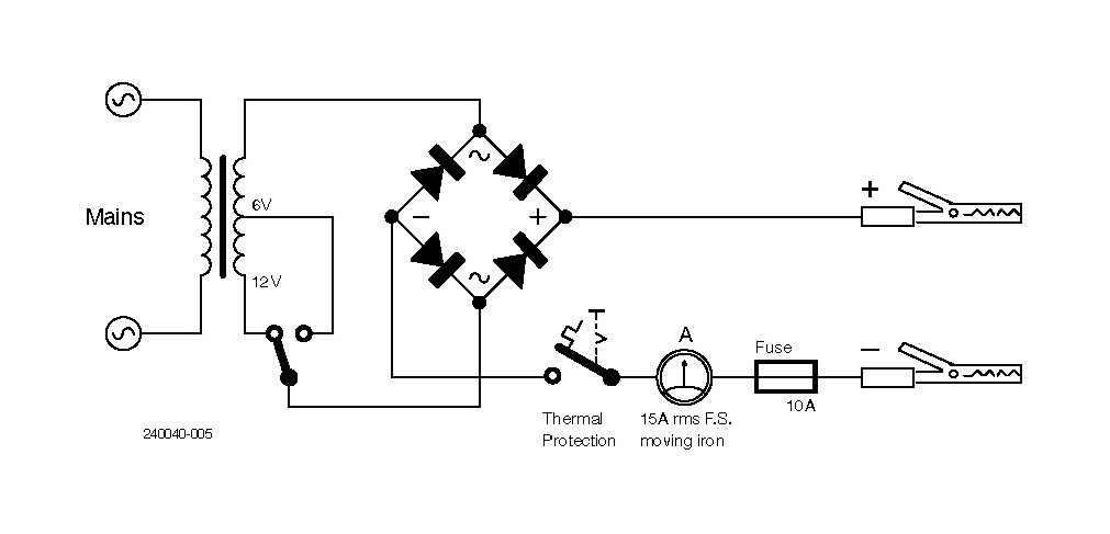
This series of projects grew out of the discovery of a new old stock (NOS) item in a friend’s garage. It was a sturdy-looking and well-painted battery charger, dating back a decade or so, which he had never used and generously donated to me. Being an engineer, obviously I◦could not resist the urge to take it apart and was surprised to note that inside it the electrical circuitry could not have been simpler: a transformer, a bridge rectifier plus one car-fuse and a moving-iron ammeter on the front panel. The only “premium” option: a 6◦V/12◦V battery selection switch. Its basic schematic is shown in Figure◦1.
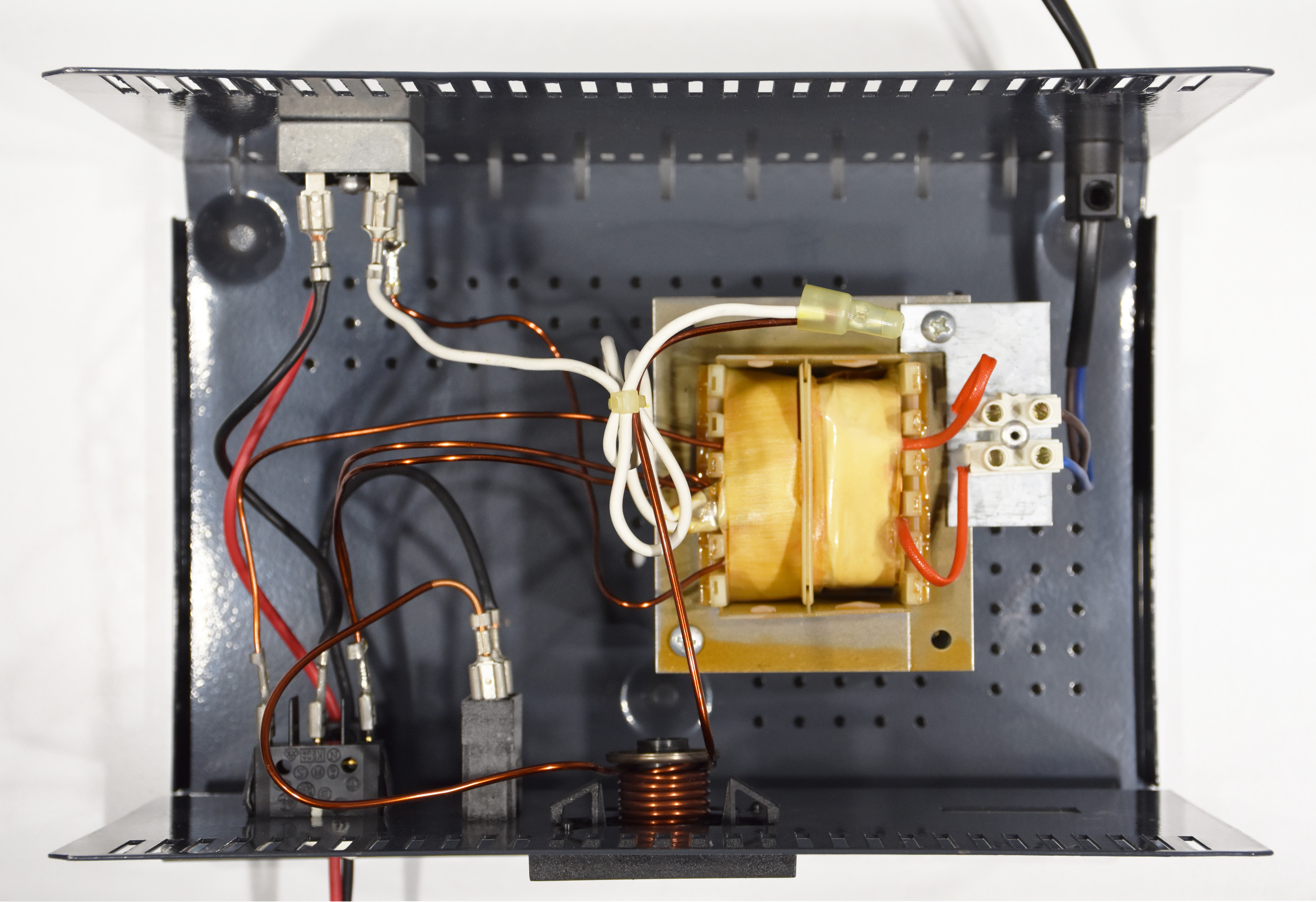
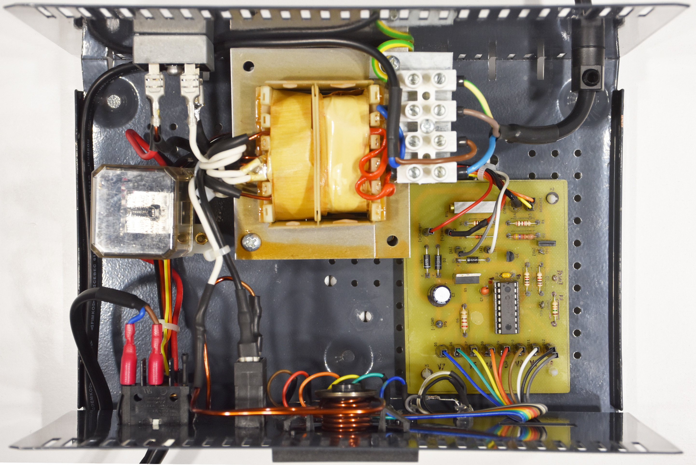
Despite the being simple, the interior was cluttered, as visible in Figure◦2.
Accustomed to current, voltage and mixed-controlled regulator circuits, it seemed to me a coarsely designed product, and aware of the criticality of using it with sealed lead-acid batteries and — even worse — the new generation of AGM batteries, I was about to throw it away.
However, in discussing it with my friend Walter Ribbert, it turned out that taper chargers are still popular and widely available on the shelf, although the competition with the actual, multiphase IC-controlled ones is getting more and more tough. Although more expensive, the micro-controlled chargers benefit from a state-of-the-art design and never put the health of the connected battery at risk. To learn more about how they work, you might read The Actual Charging Standard at the end of this article.
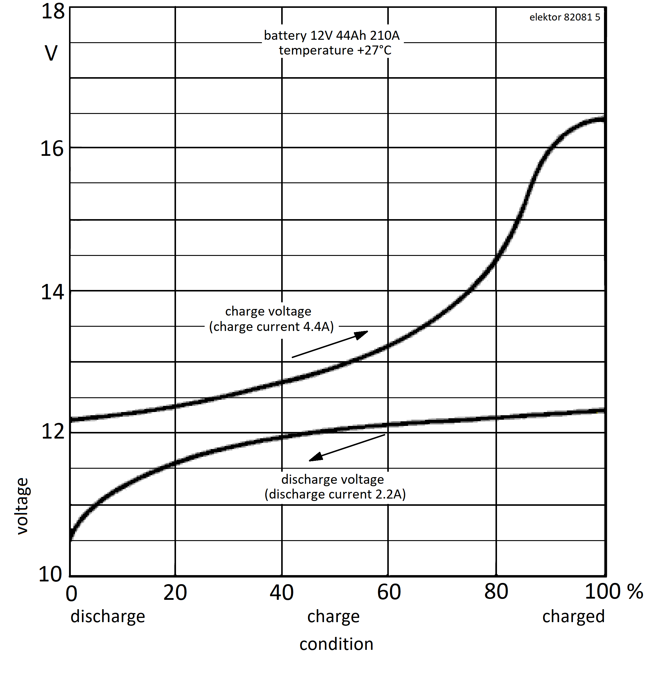
The Lead-Acid Cell Before proceeding with our design, it could be worthy spending a few words about a standard lead-acid cell’s typical parameters. It has a nominal voltage of 2◦V, and a car battery contains a series of six of these cells. Typical constant-current charge and discharge characteristic curves of a 12◦V battery can be seen in Figure◦3. As can be seen, the curves do not go below 10.5◦V (1.75◦V per element); if the voltage is lower or, worse, goes to zero, generally the battery gets damaged and can no longer be recharged. It is good to remember that this type of battery, after assembly, is activated by filling the inside of the elements with a 30…40% solution of sulfuric acid; after activation, the voltage of each element reaches about 2.1…2.2◦V.
Taper Chargers The first taper battery chargers date back to the ’50s and were equipped with selenium rectifiers that, later on, were replaced by silicon type. This type of charger is cheap to make and buy, it’s reliable — if used properly — but its operation is critical and is based solely on an accurate transformer design, with careful considerations about Vout(rms) and Zout, which were calculated for the specific use with lead-acid◦batteries.
As anticipated, it offers no control on either current or voltage, and its charging process must be followed-up carefully. The initial charging current depends on the capacity, state of charge and health of the connected battery; therefore, is largely unpredictable, and in most cases, a thermal trip switch is embedded in the transformer to protect it against overheating.
Preliminary Measurements We thought that to learn more about the behavior of a taper charger connected to a standard accumulator, it would be useful to make a series of accurate measurements, regardless of the modding solution we would envision. To obtain repeatable conditions for the measurements, the battery under test was connected to a 300◦W Korad◦Kel103 electronic load, which allowed to perform controlled discharge cycles to a predetermined threshold at 11.5◦V (=◦80%◦discharge).
To measure charge current parameters, we used an oscilloscope connected to a Pico◦TA018 low-drift DC clamp (with an output level of 100◦mV/A), with a second channel measuring two auxiliary voltage sense wires heading directly to the battery clamps, realizing a so-called Kelvin◦Connection. If you want to read more about this, you might take a look at The 4-Wire Sensing text frame at the end of this article. This way of testing made it possible to dynamically detect, in an accurate way, the relationship between the output current to the battery — 100◦Hz DC◦pulses — and the voltage changes at its terminals.
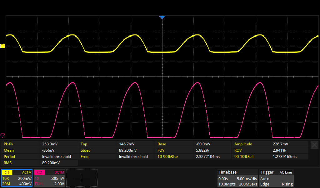
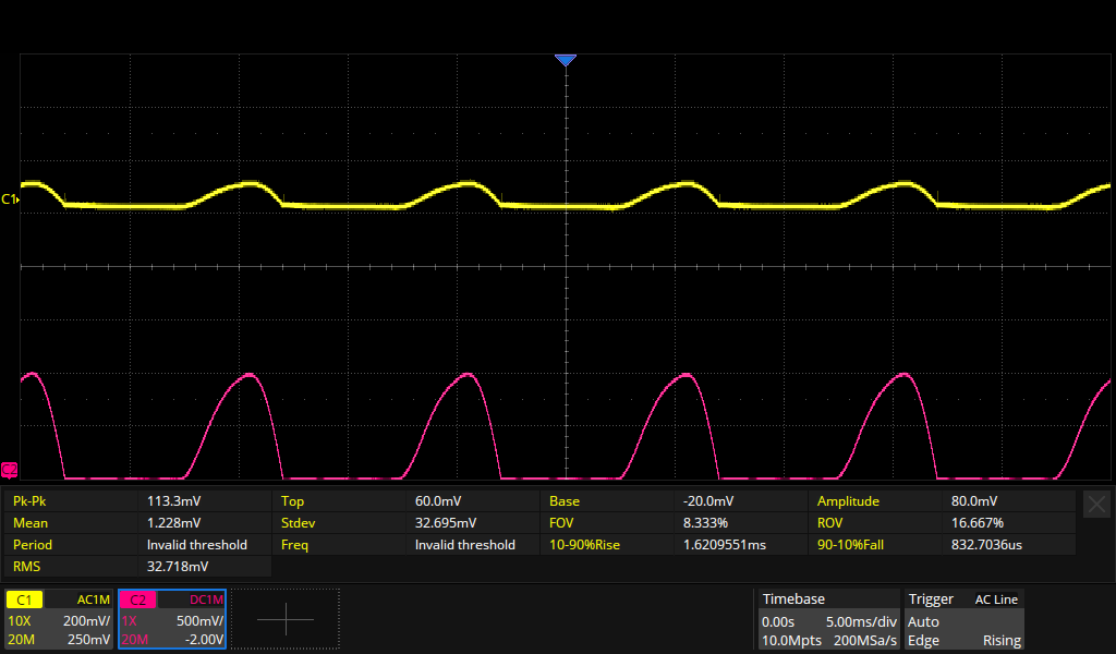
Figure◦4 shows the screenshot of the measurement of the initial charging phase (battery at 20% of its charge state). The purple trace indicates the current values, over 18.5◦A peak in this case, while the yellow one, with AC coupling, detects the voltage ripple directly on the battery, 253◦mV.
This made it possible to calculate the internal resistance value Ri of the accumulator during charging:
Ri◦=◦ΔV/I◦=◦0.253/18.5◦=◦0.0136◦Ω
Figure◦5 shows the values measured at the end of charging, when the battery had reached a voltage of 14.8◦V.
As can be seen, the charging current shows peaks of 10◦A, far too high to leave the device connected for long! Please note that in both Figure◦4 and Figure◦5, the baseline of the purple trace lays at the actual voltage of the battery (I◦=◦0, Vcharger◦<◦Vbattery), whilst the portions of the sine wave represent the time when Vcharger◦>◦Vbattery and the current flows.
So, our conclusion was that despite the draftiness of its charging cycle — and rather than dumping it — its modding would have made it safer, more useful and (why◦not...) saved some resources on the planet.
Now the challenge was how to do it, and Walter came out with the following requisites:
Protect the charger from accidental shorts of the clamps and from polarity reversal when connecting the battery.
Immediate restoring of the protection in case the clamps were disconnected from the battery, without sparking.
Add an accurate voltage check at the final stage of charging, to make the charger more usable.
Design a cooler, microcontroller-based version, for those readers who are definitely unable to refrain from coding!
Since the proper functioning of a taper charger is based almost entirely on the small differences in voltage and impedance between the charger and the battery mentioned above, it quickly became apparent that any variation in the original scheme, even modest — done by inserting semiconductors like power diodes, transistors or MOSFETs — would produce considerable variations in the charging current and, ultimately, in the effectiveness of the device. For this reason, the only possible solution seemed to be to control the charging through a power relay.
The latter could not be a standard few-amp model used in electronics, but rather an automotive type relay or a heavy-duty, high-current type (20◦A minimum) for industrial use, with a very low contact resistance. In the end, a model by Potter & Brumfield was chosen [1], with 12◦V◦DC coil and the three sets of switches connected in parallel for the applications.
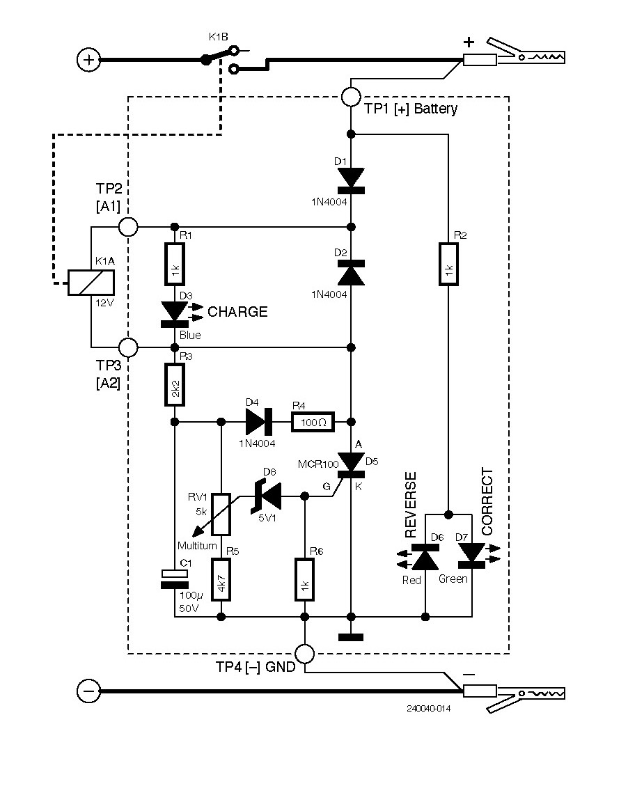
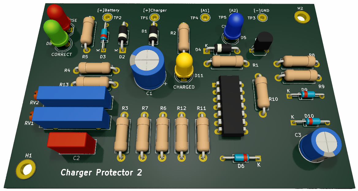
First Solution: Basic Protection According to the requirements listed above, this first design of Walter (whose schematic is visible in Figure◦6) came out. It fulfills the first two points of the requisites list, activating the relay only when the battery is connected and triggering only on a single, adjustable minimum voltage threshold. Diode D1 protects the circuit from polarity reversal of the battery clamps. The two LEDs D6 and D7 display the correct connection of these clamps: if it is ok, D7◦(green) lights up; otherwise, D6◦(red) turns on.
When the connection is correct, capacitor C1 charges mainly through the winding of K1 and R3. If the battery voltage is high enough to exceed the threshold set by RV1 and the 5.1◦V Zener D8, it drives the gate of SCR D5, which enters conduction and energizes relay K1; the blue LED D3 indicates the event, connecting the charger to the battery. Connecting the charger to the mains starts charging. Trimmer RV1 allows the relay trip threshold to be adjusted, with a minimum of about 8…9◦V battery voltage, a value that depends on the minimum operating voltage of the relay.
When SCR D5 goes on, it discharges capacitor C1 through D4 and R4. Disconnecting the leads from the battery with the charger energized D5 turns off, since its holding current is zeroed when the pulsating voltage output from the rectifier drops to zero. This ensures that the relay de-energizes and opens; the time constant R3◦*◦C1 (greater than 200◦ms) prevents the immediate re-energization of D5. This circuit works with both single-diode (half-wave) and bridge (full-wave) rectifier chargers. In this respect, it is important not to install any capacitors (unnecessary, by the way), even of small value, upstream or downstream of the relay contact of the protection circuit.
Adjustment Calibrating the tripping voltage level is simple; turn the RV1 trimmer toward R5 and, with the charger disconnected from the mains, connect an adjustable power supply in place of the battery; set it to the desired minimum voltage, e.g., 10◦V, and adjust RV1 until the relay trips and D3 turns on. Once the SCR has started conducting, it will remain in this condition even if the battery voltage fluctuates.
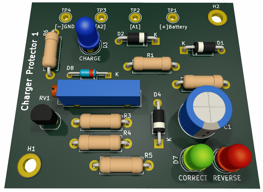
The schematic in Figure◦6 also shows how to integrate the circuit into the charger. For accurate battery voltage measurement and to avoid reading errors due to voltage drop across the power leads, the 4-wire sensing described above has been provided in this and the subsequent designs as well. The 3D rendering of this project is shown in Figure◦7.
Although the addition of protection has solved the safety aspects of battery charger use, it is still not enough to ensure the good health of the accumulators being charged. Therefore, two additional designs have been developed.
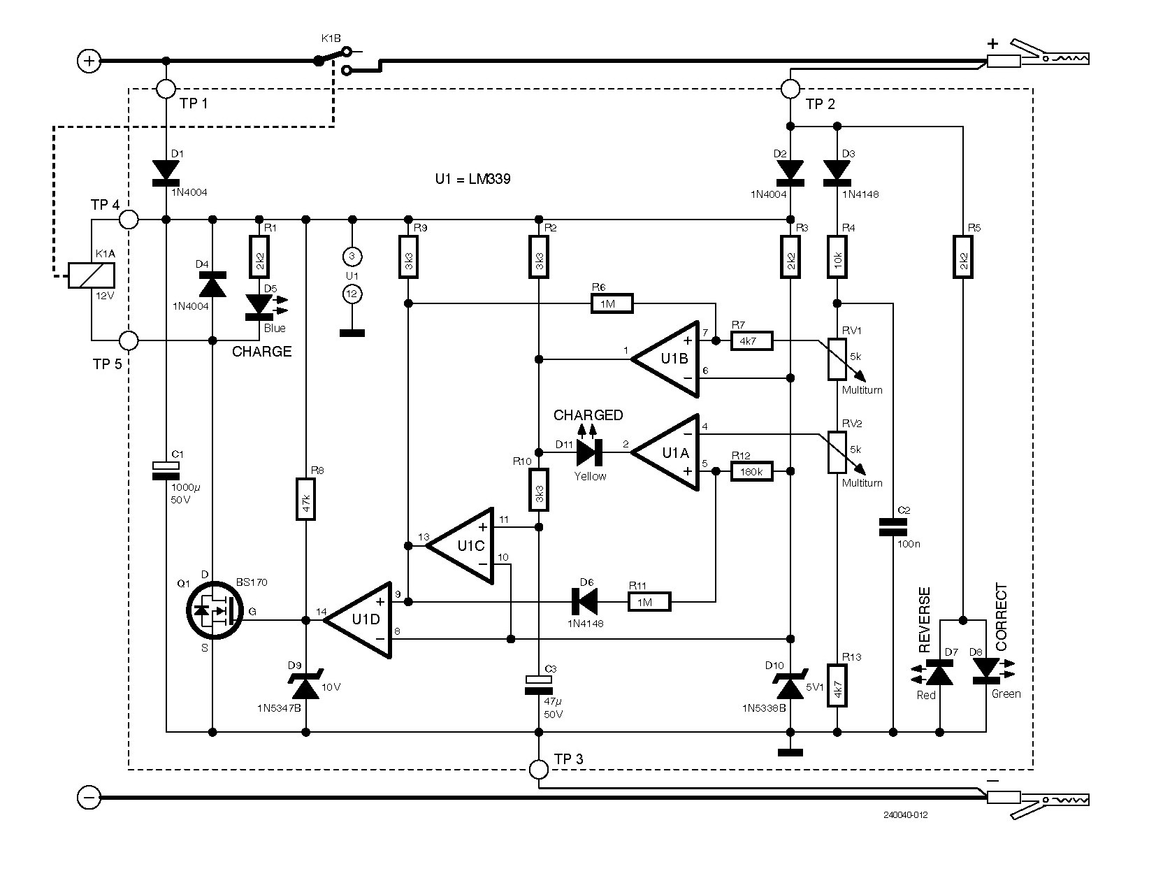
Second Solution: Protection With Voltage Control This second full-analog design offers the same protection capabilities of the first design in the previous article, but adds a voltage control that stops the charging process once the target voltage has been reached. As shown in the schematic diagram of Figure◦8, this design drives the relay using a BS170◦MOSFET, rather than an SCR.
◦Diode D1 allows the circuit to be powered through the battery charger. D2 powers it through the battery, while D2 and D3 protect the electronics from the reverse connection of the clamps. LEDs D7 and D8 (optional) display the reversed/correct connection of the clamps. The system is essentially built around U1, an LM339 quad op-amp by Texas Instruments [2] with open collector outputs, and by relay K1 driven by MOSFET BS170 (Q1).
Via signal diode D3 (1N4148), the circuit senses the battery voltage, scaled by the resistive voltage divider formed by R4, RV1, RV2 and R13. Comparators U1A and U1B compare the reference voltage of Zener diode D10 (5.1◦V) with the thresholds set on the sliders of multi-turn trimmers RV1 and RV2; both of these comparators function as Schmitt triggers.
U1B, with R6 and R7, has a hysteresis of about 0.2◦V; it controls the activation of relay K1 and turns on D5 (blue) when the voltage exceeds the threshold set with RV1 (> 7.5◦V), e.g., 10◦V, and turns it off below 9.8◦V.
U1A, with D6, R11 and R12, has a hysteresis of about 1.8◦V. It turns off relay K1 and D5 and turns on D11 (yellow) when the voltage exceeds the threshold of RV2 (> 13◦V), e.g., 14.4◦V. U1A turns K1 back on when it drops to about 12.6◦V.
U1D has the purpose of decoupling the driving stage of Q1 from the rest of the circuit, while U1C has the specific function of closing the hysteresis loops with its non-inverting input on pin 11, delayed by the RC network R10 and C3.
The automatic thresholds make it possible to leave the charger connected to the accumulator in buffer mode, interrupting the charging process before the gas-producing charge level is reached (about 14.5◦V), to preserve sealed batteries or those in which liquid cannot be added.
Even with this design, disconnecting the clamps with the charger energized causes the relay to open, but with a different dynamic than with the previous design. By disconnecting the battery, the pulsating voltage of the charger rises to its maximum value, exceeding the high threshold of the comparators and turning off the relay; the resulting voltage drop produces the tripping of the lower threshold, which confirms the event. The RC◦filter, consisting of C3, R2, and R10, prevents the reactivation of the relay during this transient.
This circuit also works with both single-diode and bridge rectifier, and again it is important not to mount electrolytic capacitors upstream or downstream of the protection circuit. The schematic in Figure◦1 is also showing how to integrate this design into the circuit of the existing battery charger. Figure◦9 shows a 3D-rendering of the populated PCB.
Adjustment
For calibrating the trip thresholds:
Move the sliders of trimmers RV1 and RV2 toward R13.
Power the circuit between TP2 [+] and TP3 [-] with an adjustable power supply to the desired charging voltage (e.g., 10◦V).
Adjust RV1 until LED D5 lights up and relay K1 closes.
Increase the voltage to the desired end-of-charge value (e.g., 14.8◦V).
Adjust RV2 until LED D5 turns off, LED D11 turns on, and relay K1 opens.
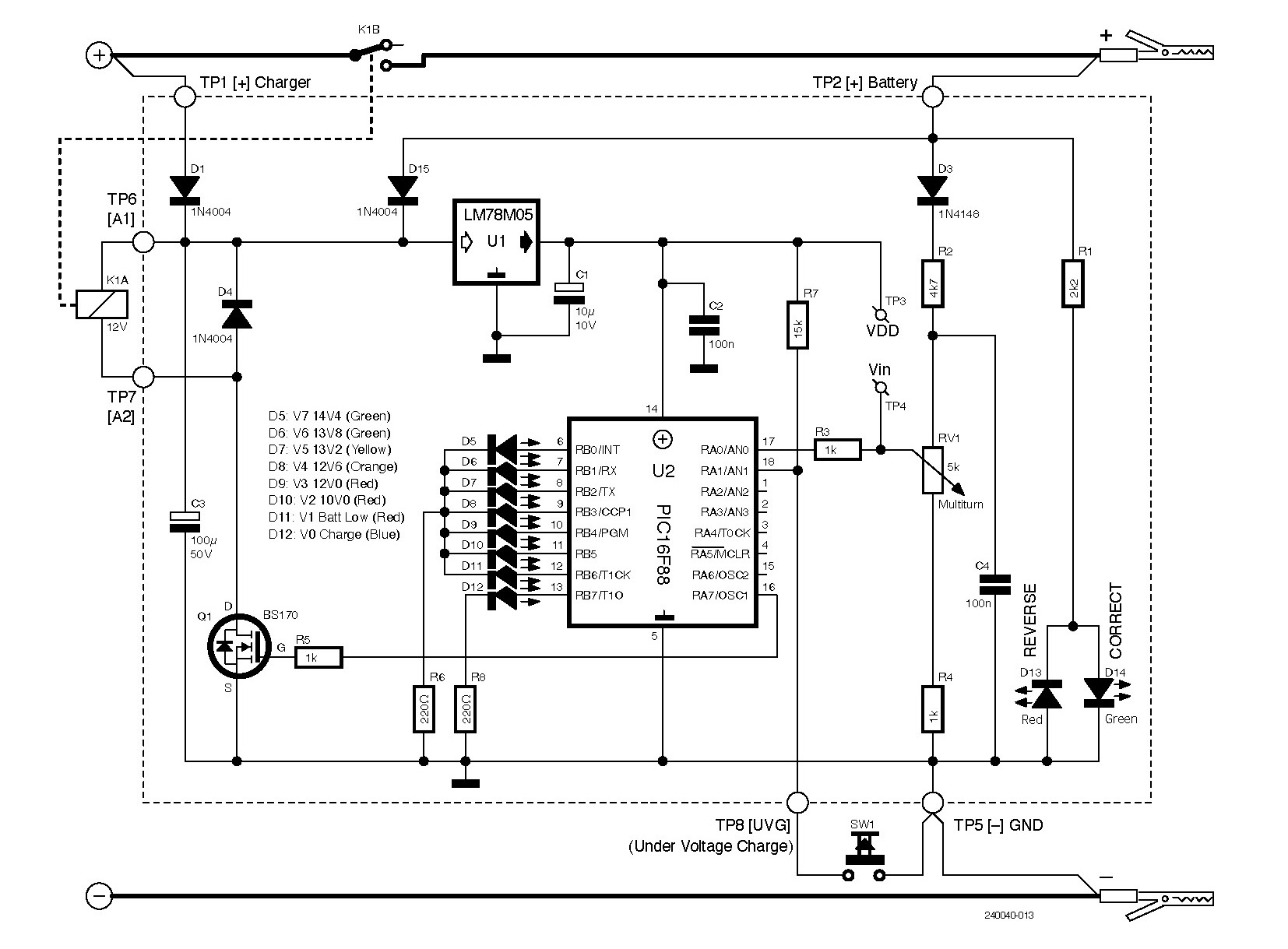
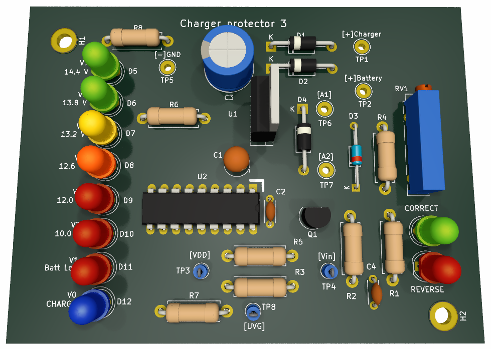
The Third, Microcontroller-Based “Luxury” Version The third and most performing circuit replicates the functionality of the second, but with set thresholds. It is built around a microcontroller, a PIC16F88 by Microchip, that measures battery voltage via a 10-bit resolution ADC◦input. The use of the microcontroller simplifies the circuit and allows the battery state of charge to be monitored with LEDs; however, it requires a 5-V voltage regulator (78L05) to power it. The schematic diagram of this third design is illustrated in Figure◦10 whilst its 3D rendering of the PCB is shown in Figure◦11.
Firmware The firmware of the microcontroller is written in GCBASIC; it is part of the complete KiCad project available for download on this Elektor Labs page. Its operating diagram is illustrated in Figure◦12. The battery voltage is measured every 10◦ms: if the conditions persist for at least 500◦ms the connection to the battery is activated by closing the control relay; as soon as a decreasing value is detected, it is deactivated, to ensure safety performance during transients.
The main activation and disconnection thresholds are:
Activation at 10◦V, with hysteresis of 0.2◦V
Deactivation at about 14.8◦V, with hysteresis of almost 2◦V
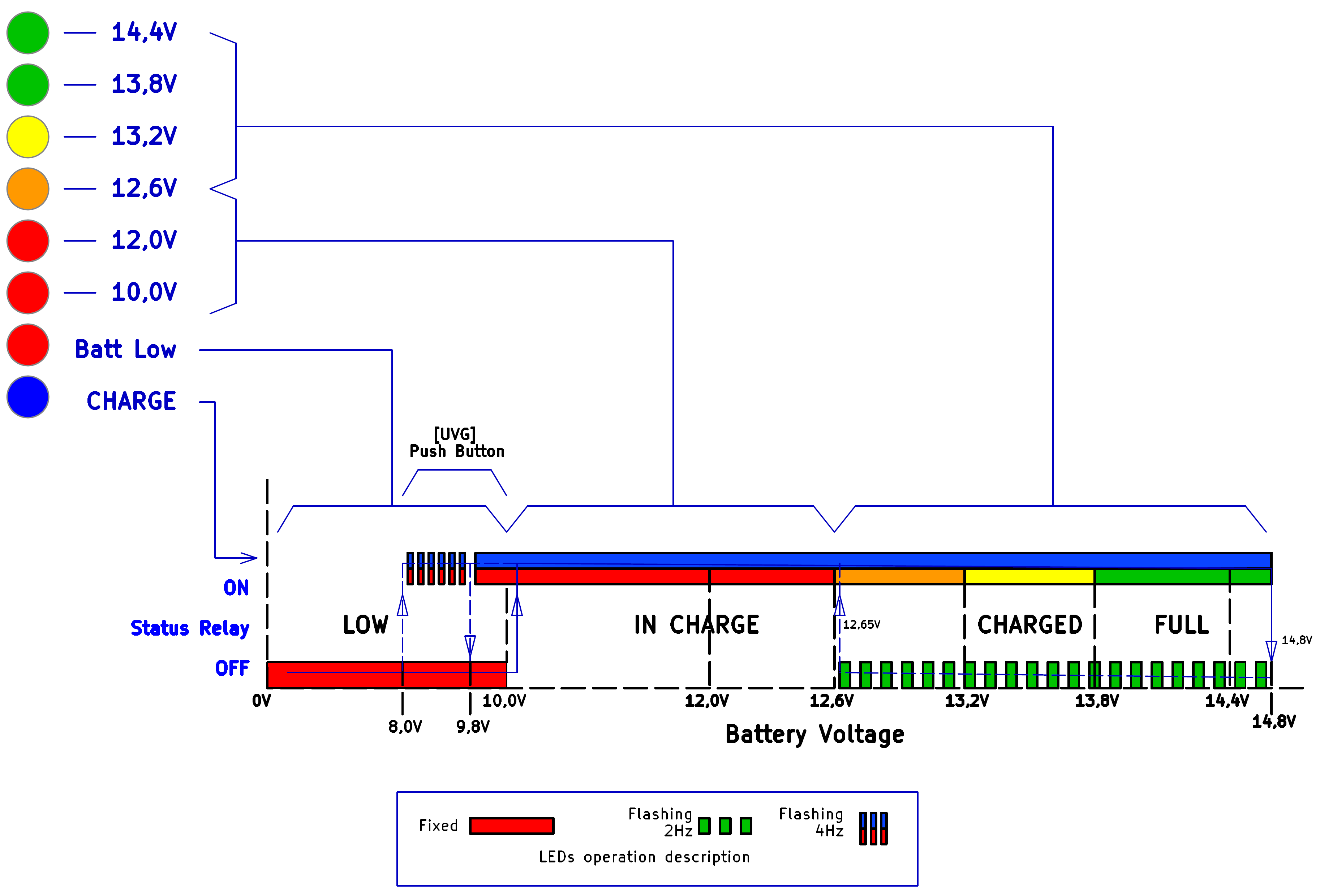
Up to 10◦V, LED◦D11 (V1, Batt◦Low) stays on, beyond that voltage and up to 14.8◦V the relay and LED◦D12 (V0, Charge) are activated and at the same time one of the LEDs D10…D5 is permanently lit, depending on the actual voltage measured at the battery clamps. When this voltage exceeds 14.8◦V, the relay is deactivated, the Charge LED goes off, the battery voltage starts dropping slowly and LEDs D5…D8 start flashing at a frequency of about 2◦Hz, following the voltage decrease.
When the battery voltage drops around 12.7◦V, the Charge LED and the relay are turned on, the charging cycle resumes with the LEDs lighting on sequentially. The hysteresis of 0.2◦V at the initial threshold of 10◦V is to avoid uncertainty in relay contact closure due to any fluctuations in battery voltage. From 10◦V to 9.8◦V the relay remains closed, Charge LED stays lit, in addition to Batt◦Low LED.
The 10-V trigger voltage, as already written, is an “indicative” threshold voltage for assessing the status of a battery; to determine whether it is in good health or not, in case of deep discharge, it is always advisable to perform a full charge cycle and evaluate the actual capacity immediately afterward with a battery tester. For these borderline cases, however, the optional SW1◦(UVG, Under Voltage Charge) “sustained action” button has been provided, which allows the relay to be activated manually from as low as 8◦V battery voltage.
It must be held pressed to achieve the function; if released, the circuit immediately resets to its default threshold; while it is held down, and until the battery reaches 9.8…10◦V, in addition to the relay activation, the Charge and Low◦Batt LEDs flash at about 4◦Hz, indicating the temporary condition. The pressing of the button will cause no reaction if the battery voltage is lower than 8◦V or higher than 10◦V.
The sampling input of this circuit is being supplied solely via the Kelvin link, through a long wire coming from the [+] battery end. Therefore, on its way it may collect electrical noise, that is shorted by C4.
This circuit, given the software management of turn-on time, is more tolerant of the presence of any capacitance mounted upstream or downstream of the relay contact; however, given their complete uselessness, it is best not to install them and to follow the schematic in Figure◦3 for the integration of this design into the charger.
Calibration Although the thresholds are fixed, to compensate for the error due to the tolerances of the components, a calibration is required. It consists of aligning the reference voltage of the ADC, which is the VDD of the micro’s power supply, with the maximum measurable battery voltage (full◦scale), set at 15.00◦V to ensure that the thresholds are read correctly. To perform this, you need to bring the slider of trimmer◦RV1 all the way to R4, power the circuit between TP2 [+]◦Battery and TP5 [-]◦GND at 15.00◦V, adjust RV1 and simultaneously measure with a DVM 0.00◦V between TP3◦[VDD] and TP4◦[Vin]. This automatically compensates for any possible difference in the rated, theoretical 5◦V output voltage of the voltage regulator and the tolerance of the resistors values of the input divider.
Despite the calibration, one factor of uncertainty remains: the voltage drop of diode D3 (1N4148), which is assumed to be typically around 0.6◦V. To determine the bit value corresponding to the expected threshold voltage with a 10◦bit◦ADC the following formula is used:
The full-scale voltage is 15◦V - VD3 (0.6◦V for 1N4148), for example:
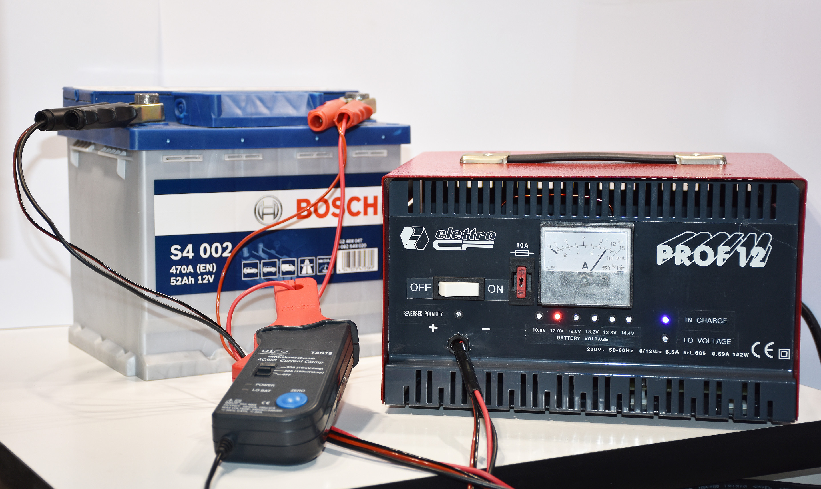
Integration in the Battery Charger As already seen in the previous article, the space inside the device was not used rationally and was not suitable for modification; therefore, as shown in Figure◦13 the transformer was moved to a more convenient position, then the connections to the 6◦V/12◦V switch were removed, eliminating the link to the center tap of the secondary winding of the transformer and isolating it. The original mains cable was replaced with a standard three-conductor type, and the safety ground connection to the chassis was added.
Next, holes were drilled for the various LEDs and related labels were arranged on the front panel. The original 6◦V/12◦V switch was given the more useful function of main ON/OFF switch. The power relay found its place near the bridge rectifier. The control board was placed to leave the connections to the (many) LEDs as neatly as possible. Figure◦14 illustrates the finished charger at work. The thin red and black voltage sense wires from the battery clamps were connected to the respective inputs on the microcontroller board.
Before Connecting the Clamps... ...it should be considered that a lead-acid battery emits a highly explosive mixture of hydrogen and oxygen during charging. Therefore, it is essential to comply with safety regulations and always work in a well-ventilated environment. Before connecting the clamps to the battery ends, check if your garage (or workshop) has these features. Furthermore, if you don’t know the characteristics of the electrical system of your car or motorcycle, it is always best to proceed with off-line charging (i.e., disconnecting the battery before proceeding).
The last-generation of (offline) Lead-Acid battery chargers are working in well-defined subsequent phases:
Bulk Phase
Acceptance Phase
Float Phase
Equalization (option)
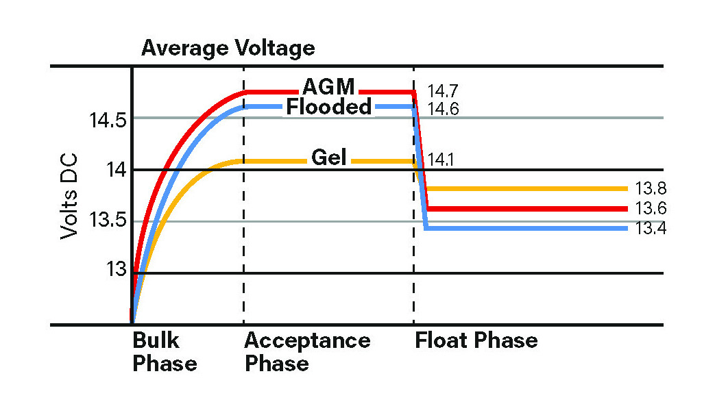
In the Bulk Phase the first, massive part of the charging process occurs. Here, in a fully controlled charger, the current limiter is activated and the charging current reaches the set maximum value. Ideally, the initial current limit should stay between 20% and 40% of the battery capacity C. For example, the 12-V, 52-Ah battery used in our tests should be charged at a rate ranging from 10 A to a maximum of 20 A. At the end of this phase — that corresponds roughly to 75% of the overall charge — different average voltages should be considered, according to the type of the connected battery, as shown in Diagram A.
Diagram A: The phases of charge in a state-of-the-art charger, with thresholds values that change according to the different battery chemistry.
Once the initial average target voltage has been reached, the Acceptance Phase starts. This is a typical voltage-controlled stage, where the set voltage threshold is maintained steady for the last 25% of the charge and the current decreases slowly up to the point where it reaches 2…4% of C (from 1.04 A to 2.08 A in our case) and we can consider the accumulator as fully charged.
In the following step, the Float Phase, a further reduction of the target voltage is performed. The purpose is to avoid an excess of gas production on the lead electrodes, with the subsequent loss of electrolyte from the cells. This phase may not be considered as a charging phase, but rather a maintenance one.
The Equalization Phase (not shown in the graph of Diagram A) is an optional one, due to its aggressive behavior to the battery. Its usage is aimed at the recovery of partially sulphated accumulators. If included in the cycle, it occurs just after the Acceptance Phase at a continuous charge rate of 4%, until the absolute maximum state of charge — and voltage — is reached. It usually stops around 15.5…16.2 V, and for this reason, it's not suitable for AGM and Gel types of lead accumulators. Even with the flooded type, however, limited to offline charging (i.e., with the battery disconnected from the system) and for a limited number of cycles, due to the wear that this process involves.
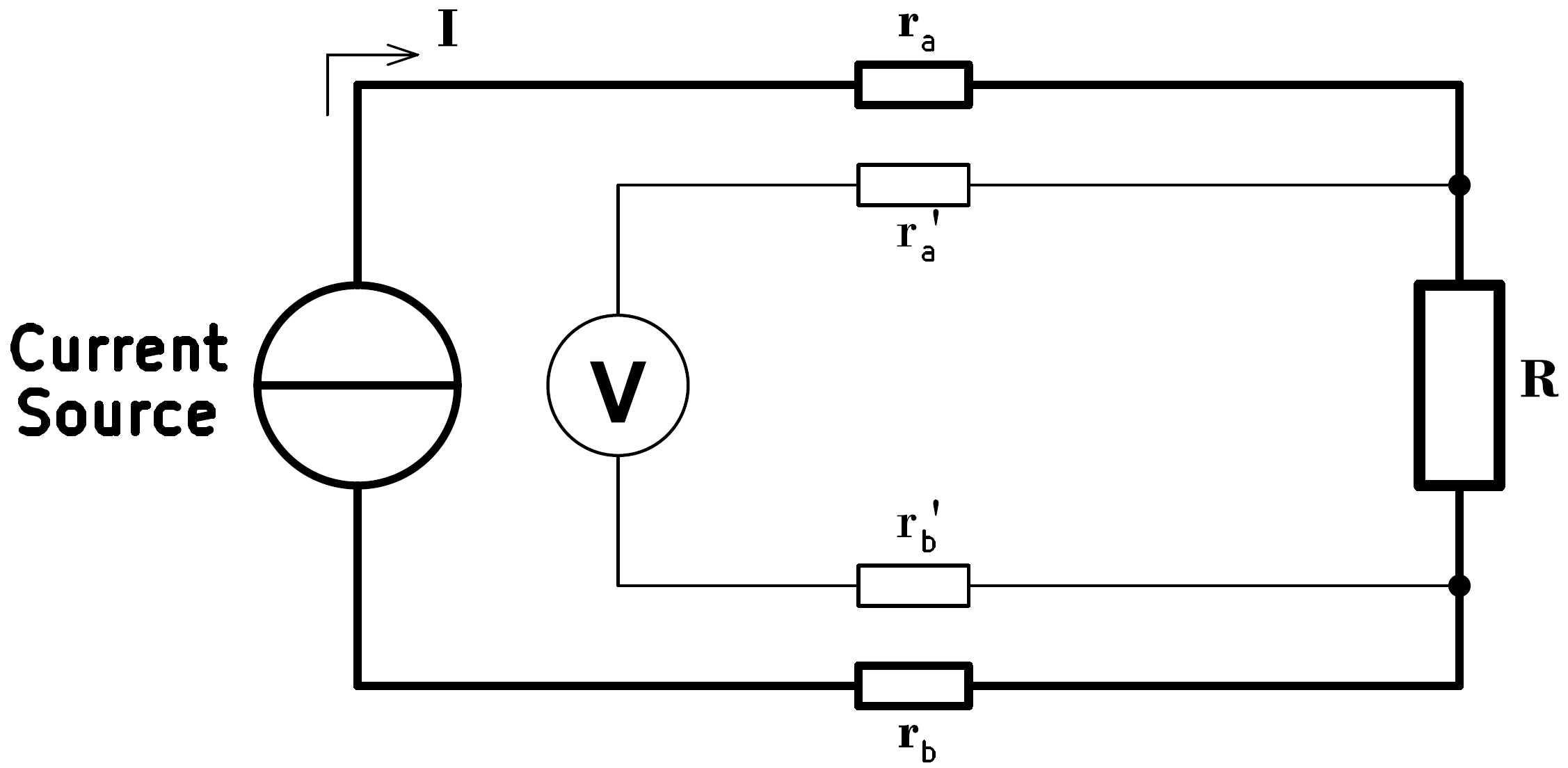
The 4-Wire Sensing The 4-wire Sensing technique, also known as Kelvin Connection, gets its name from the English physicist who invented it in 1861. The principle on which it is based, as shown in the diagram, is to separate the load cables with internal resistance ra and rb, intended to carry the current I to the load R (a battery, in our case), from those (r'a and r'b ) designed to measure the voltage through a Hi-z sensing circuit, which follow a separate path. In this way, the voltage drop Vdrop = (I*ra+I*rb) — from the current source to the ends of the connections carrying it to R — becomes irrelevant even as the current I varies, since the voltage measurement always takes place directly at the terminals of the supplied device, often referred to as the Point of Load in industrial settings. This 4-wire connection allows to measure the value of R very accurately, even in the case of extremely low-Ohm values.


Discussie (0 opmerking(en))