

Platino Soldering Station [140107 ]

A simple Platino based soldering station for not too demanding (hobbyist) applications. Temperature range of 90 – 450 degrees Celsius with temperature readout on an LCD.
NEW Firmware ready
See also the SMD Soldering Station for Weller Soldering Tips [140010-I] for more discussions about this project.
Related Elektor Magazine articles
Platino Solder Station, issue 7, 2015
Platino - Versatile Board for AVR Microcontroller Circuits, issue 10, 2011
Platino, the return, issue 3, 2016
Introduction
A simple Platino based soldering station is designed for not too demanding (hobbyist) applications. This Platino based soldering device can be used to heat up the soldering bit to a temperature ranging from 90 – 450 degree Celsius and also to check the temperature of the soldering bit.
The project is about a cheap SMD solder station built as a Platino Add-on system. It supports active soldering tips from Weller (RT series) which contain the heating element as well as a sensor and a standard 3.5 mm jack. Together with the corresponding female connector you will get a compact SMD soldering iron with very fast heat up times of a few seconds. Also support similar soldering bit. The Add-on board consists of a low-noise amplifier for measuring the temperature via the ADC of the AVR, a power MOSFET stage to control the heating using PWM, LCD display and encoder for setting and displaying the temperature.
The elaborated design of the Elektor Platino board makes it easy to extend its capability, to develop devices of complex functionality with only a few additions.
New Firmware:
The current firmware lacks some features that are essential to prevent the tips from getting burned. Also the hardware needs a modification to have the detection working as desired. You need to add a 1Meg Ohm resistor between VCC ( 5V ) and the sensor input. This can be done at the IC2 by connection the resistor between pin 8 ( VCC ) and extend it with a wire to the sensor terminal. This is not a nice looking mod, but will be the only way to have good detection if the sensor fails.
The problem is, with bad contacts if the sensor disconnects you have a open input at the opamp and the values will be just random within a range of 50 to 460 degree. Also if the iron cant reach it's temperatur for a given time the sofware will trip a fault and shutdown.
A few new goddys also are now in the software, an automatic standy if the tip is not used. This means the station redices the temperatur to 100°C and a press on the rotary button brings it back to the desired value. Also there is a standby now if the station was 10 minutes in powersave the station will enter standby an cut power to the tip totally. A press on the rotary buttion will get the station alive. Also as the old software was written for the Atmel Studio 4, we decided to move it back to the Arduino framework, to give you the posibility to easily add new functions on your own. The surce of the new firmware is now on github and also you find prebuild hex-files as attachment.
About Platino:
First published in Elektor Magazine October 2011.
Platino 1.4 is published in Elektor Magazine March 2016
The name Platino is a playful reference to the French (and German) word ‘Platine’ meaning ‘circuit board’, with a slight wink at ‘Arduino’. It is a versatile circuit board for circuits based on an 8-bit AVR controller. With an ATmega168 or ATMega324 Platino can play the lead role in a large number of sketches. And for the most demanding builders it has a convincing trump in hand: it can be fitted with an ATmega1284!
Platino 1.4 is backwards compatible with Platino 1.3. Note that it has two extra jumpers for the LCD (JP15 & JP16) and that diode D1 was added to protect the FTDI cable. Mount D1 if the FTDI cable must be able to power the board (during MCU programming for instance).
Specifications:
- DC Input: 12V to 15V DC
- Elektor Platino with ATmega328P microcontroller.
- 16 X 2 LCD Display
- 3 way terminal block for connecting 3.5mm stereo jack socket for connecting weller RT series soldering bit.
- Heating temperature ranges from 90 – 450 degree Celsius.
Features:
- The heating is controlled by the PWM using Platino MCU
- Displays the current soldering bit temperature on LCD.
- Rotary encoder to vary the soldering bit temperature.
The Platino-based Soldering station is divided into two major sections one the hardware and another is software, both are responsible for the stability and accuracy of Input and output. The heart of the project is the PLATINO MCU board which contains MCU ATmega328P.
The Hardware consists of two sections
- Platino MCU board with LCD
- Soldering station Add-on Board.
Platino MCU board with LCD:
Platino Series is easy to use for developing AVR MCU based applications just by adding simple add-on board of supporting functions at input stage. This board supports the LCD depending upon the requirements and also the AVR MCU depending upon functions to be performed by the circuit. Here platino consist of ATMega328P MCU and 16X2 LCD with backlight. The board reads the temperature of the sensor signal through the MCU board on pin PC0 of MCU and displays the soldering bit temperature on LCD. Also the PWM generated by the MCU on pin PB2 is used in controlling soldering bit temperature. The PWM is generated on the basis of the temperature set to heat the soldering bit. To set the required temperature the platino board consists of a rotary encoder for easily varying the required temperature. The set temperature is also displayed on LCD. This board powered from add-on board at 5V supply voltage.
Soldering station Add-on Board
The Add-on board consists of a low-noise amplifier using IC2a OPA2336 for measuring the temperature. The heater and sensor output from the weller soldering bit is connected to 3.5mm stereo socket to add-on board through connector K1. The sensor signal connected to IC2a non inverting pin 3 through resistor R1 and output of IC2 at pin 1 connected to PC0 pin of platino MCU for reading temperature of soldering bit.
Transistor T1 is used to control the temperature of the soldering bit whose gate is control by transistor T2. PWM signal from pin PB2 of platino MCU is connected to gate of transistor T2 via resistor R6.The circuit can be operated from 12 V to 15V DC supply with 2.5 to 3A current rating.
The power can be connected to connector K6 on add-on board. This board also contain 5V regulator for generating 5V for add-on board as well as platino board. IC1 MC7805 is used for generating 5V supply. The board also consists of a MOSFET for controlling the soldering bit temperature.
Software:
The software for the project is written in AVR Studio for ATMEGA328P microcontroller. The Platino board is used for further development of the project.
The software reads the temperature of the soldering bit via MCU ADC pin PC0 and displays the current temperature of the soldering bit on the LCD and allows the user to set the temperature of soldering bit using the rotary encoder.
The heating of the soldering tip directly takes place from the MOSFET from the actual temperature to 5 degree Celsius less than set temperature. Above 5 degree from set value to the set value the soldering bit is heating using the PWM from MCUvia PB2 pin. If the actual temperature goes above the set temperature value then the MOSFET is switched OFF.
The ADC of the MCU periodically reads the temperature of the soldering bit and adjusts the temperature as per the set temperature value using PWM
Building the Prototype:
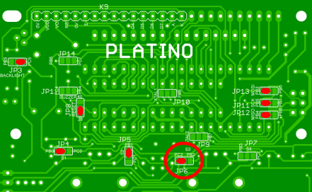
First ‘Jumper’ the platino board as shown in Table 2. The other components should solder after placing the required jumpers.
Note: this project uses Platino v1.3, for Platino v1.4 and higher place JP15 & JP16 in postion 'D'. Also you may need to mount diode D1 if the board must be powered by the FTDI cable (during MCU programming for instance).
Now build the Platino with its LCD, rotary encoder, ATmega328P MCU and all other components. Refer to the Platino component list below to find out which parts must be mounted. Please take care that you mount the MCU on the same side as the LCD and the rotary encoder.
The add-on board that consists of the main circuitry for the soldering station that is connected to the Platino board via connectors K2 and K3. The Add-on board of soldering station is so designed to fix exactly to the back of Platino board with the help of connectors.
Testing:
- Connect the 3.5mm stereo socket to connector K5 and plug the TR1 soldering bit in it.
- The device is powered up through connector K6 with 12V DC adapter.
- Set the temperature for heating the soldering bit using the rotary encoder.
- The LCD will show the actual temperature of the soldering bit.
- As the temperature of the soldering bit reaches the set value you can use the soldering bit to solder SMD component on PCB.
| Pin designation | Function |
|---|---|
| PB0, PB1 | Rotary encoder |
| PC2 | Rotary encoder push button |
| PB2 | PWM output |
| PC5 | LCD backlight control |
| PC0 | Temperature sensor ADC input |
| Jumper | Position |
|---|---|
| JP3 | PC5 |
| JP4 | PB0 |
| JP5 | PB1 |
| JP6 | PC2 |
| JP8 | '28' |
| JP11 | PB5 |
| JP12 | PB4 |
| JP13 | PB3 |
| Platino v1.4 & higher | |
| JP15 | D |
| JP16 | D |
Component List Platino
Resistors, all 5%, 0.25W
R3 = 47Ω
R4, R5, R6, R7, R10, R12 = 10kΩ
R11 = 4.7kΩ
P1 = 10kΩ trimpot, horizontal
Capacitors
C5, C6 = 100nF, 0.2” pitch
Inductor
L1 = 10µH
Semiconductors
IC1 = ATmega328P-PU, programmed (Elektor Store # 140107-41)
T1 = BC547C (Platino 1.3) or 2N3904 (Platino 1.4, or BC547 mounted on LCD side)
D1 = 1N5817 (Platino 1.4 only)
Miscellaneous
S5A = rotary encoder with integrated pushbutton (Alps EC12E2424407 or equivalent)
K2, K6 = 6-pin pinheader, 0.1” pitch, straight
K3 = 6-way (2x3) pinheader socket, 0.1” pitch, straight
K5 = 8-way pinheader socket, 0.1” pitch, straight
K9 = 16-way pinheader socket, 0.1” pitch, straight
LCD1 = LCD, alphanumeric, 2x16 (Elektor Store # 120061-74)
DIP28-narrow IC socket
Discussie (18 opmerking(en))
Ulf 6 jaar geleden
i have sent a request to support, but I want to be safe.
best regards
Ulf Holt
Ulf 6 jaar geleden
I have asked to compile two version, one with support for clock wise rotary switch and one for the anti clock wise version, since my rotary switches was working in the oposite direction of the switches that was reccomended.
audiofan 7 jaar geleden
There is a new diode D1 to the right of K2 (plationo pcb). It is required but not mentioned anywhere. Any shottky type starting with 20V/1A will do. But it must be a shottky type. Platino gets his VCC via K2, pin 3 from the solder station pcb. D1 shall protect platino against accidential reverse polarity. See schematics of Platino v1.4b sheet3. Without D1, platino is missing VCC.
Two jumper pads (JP15/JP16) have been added, which are only documented on schematic page 2. They both must become strapped to D. Otherwise the display is missing RS end E.
Some more remarks from me:
You don't need a BS170 for T2 (solder station PCB). Any standard NPN will do. I used a BC337 without any problems.
C1 with 10nF on solder station PCB is way too small. I experienced a massive 50 CPS hum that made the temprature readout jumping around between 30 and 300 degrees. You may use a tantalum capacitor in the range of 4.7 to 10uF instead.
I argue wether OPA2336 is really required. Any rail to rail capable OP will do. And there is an option to use a single op with offset adjustment. Or opt for an cheap analog switch instead, you can even do an auto offest calibration by software.
Furhermore I hate big radial electrolytic capacitors. Especially if there is enough space left on the pcb. They needlessly increase the board height and are more sensible to vibration. Finally they complicate board assembly.
From my experiences I advice everyone to connect a 1k reseistor instead the actual heater of the weller tip to do a smoke test. I send my first tip to heaven due to these hum problems. The sensor must be connected of course. Use the cable chosen for later productive use also for testing to see if there are any hum problems. And really do that smoke test before assemling the solder station into its cabinet,
Ulf 7 jaar geleden
Any idea why?
I hav not had any problems using 10 nF, and changing C1 to 10 nF on the new soldering board, solves the problem.
audiofan 7 jaar geleden
That is, the article describes D1 as a protection against problems due to the additional supply voltage provided by the USB/seriell cable. That, in case of solder station, this diode is required so that platino gets its supply voltage at all, is not so obvious.
And I overlooked JP15 and JP16. They are mentioned right on the first page in the section about the second serial interface. But solder station does not use a second serial. So I can skip this ;-), cant't I?
This is just the proof of Murpy's law. No criticism. I wanted to give some hints to other readers. Especially experienced developers like me tend to read a manual not before something goes wrong ;-)
ClemensValens 7 jaar geleden
If you read the project description above carefully you will find that D1 is mentioned there (just before the specifications) and so are JP15 & JP16. They are mentioned again (in italic) in the section "Building the prototype" and in JP15&16 once more in Table 2. Actually, there has been an article published about Platino v1.4 that mentions most changes (I agree, some we failed to mention): https://www.elektormagazine.com/magazine/elektor-201602/28827
Ulf 8 jaar geleden
I am on a winter vaccation in Thailand, and will not be back in Norway until midle of March next year. I have most of the information I am asking about on my PC in Norway, but it is stowed away since we are renting out our apartment in Oslo while we are in Thailand.
As you might remeber, I am working on a project where I want to make a SMD version of the Platino Soldering station. I am a bit confused about the jumper settings, and I observe that in one article JP6 is not set, and in this article JP6 is set to PC2. JP7 is not set in any of these articles, and I cannot find where R7 should be connected.
Can you please help me out?
Best regards
Ulf Holt
ClemensValens 8 jaar geleden
JP7 is not used because there are no other switches connected. If you want to set it, connect it to PC3 as PB3 is used by the ISP connector K3. You can mount R7 if you like, it will do no harm.
Ulf 8 jaar geleden
Best regards
Ulf
DG4EK 8 jaar geleden
Regards
Peter
DG4EK 8 jaar geleden
Please check the website 1x a week. If it becomes available
you will find it at the main page as well as the electronic
kits you sure saw there.
Peter
Ulf 8 jaar geleden
I tried to check at Ascel Electonics, but honestly spoken, I'm not sure what to look for.
All the best from
Ulf
Ulf 8 jaar geleden
All the best from
Ulf
Ulf 8 jaar geleden
ulf
HaSch 8 jaar geleden
Maybe USB cable is too thin for the needed current. I took thicker wires.
Hans
Ulf 8 jaar geleden
Ulf 8 jaar geleden
Thank you so much for your advice. What size did you use on the silicon tube? Recon I must be able to put it inside the jack plugs
Best regards
Ulf
HaSch 8 jaar geleden
STEPHAN VAN DIJCK 8 jaar geleden
I have build according to the July/August article with PLATINO V 1.4. I have added a diode on the board in D1 to power the PLATINO. I used a 1N914, would that be right?
Initially the display was not showing anything, so per description of the PLATINO (article 10-2011), I have now bridged emitter to collector on T1, and now I do get a reading, only with "black" blocks on line 1 of teh display. I read somewhere on a post that T1 as BC547C is not right?
Any tips you can give to activate my display reading?
STEPHAN VAN DIJCK 8 jaar geleden
rjv 8 jaar geleden
STEPHAN VAN DIJCK 8 jaar geleden
Now one last question. What do you have to do to get the backlight going on the LCD?
STEPHAN VAN DIJCK 8 jaar geleden
ClemensValens 8 jaar geleden
The solder station was done with Platino v1.3. V1.4 has extra jumpers JP15 & JP16 for the LCD, see table 2 in the main description higher up. You must set them to the D position for this project.
T1 can be a BC547C but you must mount it on the LCD side of the v1.4 board. But I don't think it is used in the software so bridging collector and emitter is as effective.
Your D1 is fine, it is only needed when you program the microcontroller with an FTDI cable and you don't apply external power.
Ulf 8 jaar geleden
Best regards
Ulf
rjv 8 jaar geleden
Ulf 8 jaar geleden
Ulf 8 jaar geleden
I have two questions:
1. Is this a violation of any copy rights, if so I stop my plans
2. Is it possible to find schematics that covers the whole project - have tried to follow the schematics for the Soldering board, which is very simple, but following all the jumper settings etc on the schematics for the Platino is not so stright forward.
Best regards
Ulf Holt
Ulf 8 jaar geleden
THANK YOU SO MUCH for taking time!
All the best from
Ulf
ClemensValens 8 jaar geleden
If during the import you receive some strange error about System.Collections.Immutable then you have hit a AS7 bug that can be worked around as decribed here, post #12 by juergs. Note that after the modification you must run Atmel Studio once as administrator, afterwards everything is fine (until you hit a new bug).
Ulf 8 jaar geleden
Ulf 8 jaar geleden
ClemensValens 8 jaar geleden
Ulf 8 jaar geleden
Why don't you add a jumper setting for switching the contacts on the rotary encoder, since it looks like they come in both versions, and it would be nice to have this option in case you have ordered the wrong version, as I did. I am implementing this on my version. Using the the ATmega328P 32 TQFP to save space and avoid rewriting the code. The LCD is a bit bulky, but don't know about anything lighter.
Regards
Ulf
ClemensValens 8 jaar geleden
Ulf 8 jaar geleden
Which C-compiler are you using?
ClemensValens 8 jaar geleden
Ulf 8 jaar geleden
ClemensValens 8 jaar geleden
When you do a redesign you will make it different (and probably simpler) and it will be your design. There are no patents involved (as far as I know) in our design so you must only worry about your onw stuff. Personally, I would replace the microcontroller (too big) and so the software must be modified. You may use a different display, maybe add an extra pushbutton, so in the end your design will probably be completely different. You are free to do that.
You are not allowed to commercialize perfect copies of our design.
There are no simplified schematics, a nice exercise for you.
Ulf 8 jaar geleden
Best regards
Ulf
ClemensValens 8 jaar geleden
Ulf 8 jaar geleden
C:\Program Files (x86)\Arduino>avrdude -c usbtiny -p m328p -U flash:w:Platino_soldering_station.hex:i -U hfuse:w:0xd9:m -U lfuse:w:0xe2:m
avrdude: AVR device initialized and ready to accept instructions
Reading | ################################################## | 100% 0.02s
avrdude: Device signature = 0x1e950f (probably m328p)
avrdude: NOTE: "flash" memory has been specified, an erase cycle will be performed
To disable this feature, specify the -D option.
avrdude: erasing chip
avrdude: reading input file "Platino_soldering_station.hex"
avrdude: writing flash (6054 bytes):
Writing | ################################################## | 100% 17.99s
avrdude: 6054 bytes of flash written
avrdude: verifying flash memory against Platino_soldering_station.hex:
avrdude: load data flash data from input file Platino_soldering_station.hex:
avrdude: input file Platino.hex contains 6054 bytes
avrdude: reading on-chip flash data:
Reading | ################################################## | 100% 10.94s
avrdude: verifying ...
avrdude: 6054 bytes of flash verified
avrdude: reading input file "0xd9"
avrdude: writing hfuse (1 bytes):
Writing | ################################################## | 100% 0.02s
avrdude: 1 bytes of hfuse written
avrdude: verifying hfuse memory against 0xd9:
avrdude: load data hfuse data from input file 0xd9:
avrdude: input file 0xd9 contains 1 bytes
avrdude: reading on-chip hfuse data:
Reading | ################################################## | 100% 0.03s
avrdude: verifying ...
avrdude: 1 bytes of hfuse verified
avrdude: reading input file "0xe2"
avrdude: writing lfuse (1 bytes):
Writing | ################################################## | 100% 0.03s
avrdude: 1 bytes of lfuse written
avrdude: verifying lfuse memory against 0xe2:
avrdude: load data lfuse data from input file 0xe2:
avrdude: input file 0xe2 contains 1 bytes
avrdude: reading on-chip lfuse data:
Reading | ################################################## | 100% 0.03s
avrdude: verifying ...
avrdude: 1 bytes of lfuse verified
avrdude: safemode: Fuses OK (E:FF, H:D9, L:E2)
avrdude done. Thank you.
I have some trouble with my installation of the arduino software, so I had to copy the .hex file to the home directory for the installation to make this work.
Have now put together 3 soldering stations, since I have 3 different locations. All works perfect.
All the best and good luck
Ulf
Ulf 8 jaar geleden
Have just finished assembling the soldering station, to observe that display is not showing anything and no heat on soldering tip.
Have triple checked jumpers and soldering, and since I don't have a proper schematic for the use of Platino (sorry, its to hard to follow the connection via all the different jumpers on the board) it's hard to trouble shoot.
Have checked 5 V OK, so it might, of course be, that I have tried to program the Atmega238P-PU myself, and not been able to set efused to 0xFF or that USBtiny and avrdude is not the proper way for programming. I could, of course, order a pre-programmed chip, but I have at least 10 chips I can program, and if I order, I have to pay shipping in adition.
I think this is strange, since everybody else seem to make it go on the first run, and I have done a lot of soldering in my life, though I didn't work in that kind of business.
Any bright ideas?
Regards
Ulf
ClemensValens 8 jaar geleden
Ulf 8 jaar geleden
Looks like I have got a wrong encoder - didn't know there were different kinds and as far as I remember it was only specified a rotary encoder.
Changed the jumper connection, and works perfect now.
Ulf
ClemensValens 8 jaar geleden
You can also modify the firmware, of course.
Ulf 8 jaar geleden
Ulf 8 jaar geleden
I have the schematics for the soldering station, but not for the totalt scenario, that is components on Platino and Soldering station put together. If D1 was added on version 1.4, that's the reason I did not think about it - the articles I have read are based on 1.3 an older.
ClemensValens 8 jaar geleden
P.S. You said you have Platino version 1.3. D1 on Platino is a 3-color LED, so you must must mean D2. Or do you have a v1.4? Or both? On v1.4 the 3-color LED was renamed to LED1 and D1 was added. This diode is mentioned (but not by name) & explained in the article from March 2016. D2 is mentioned in the first article from October 2011. All diodes are of course shown in the schematic.
Happy soldering!
Ulf 8 jaar geleden
I don't know wether to shot myself or just fall on the floor laughining my head off, but it was SO simple, when I looked at Platino board and observed the D1 diode, which, as far as I can see, is not mentioned in the article. Found general purpose diode and soldered in, so the Platino gets its 5 volt - had just checked that the pin into the board had +5 and took it for granted that this was OK. Now both cards are working, and my next step is to order a bunch of PCBs for the soldering station from my PCB vendor - want to run this as a project with some friends.
I am so sorry for all the trouble I have been causing. I know from several years of trouble shooting in the IT business that you should always start with the obvious things, but may be it would be an idea to say the D1 is needed to give power to the Platino board. Could not find it in the text, but I might have missed it.
All the best from
Ulf
(Just hope I did not give you too many sleepless nights
ClemensValens 8 jaar geleden
Please be more specific. "Programming worked fine with no errors" Does this mean that the eFuse verification error is gone? What exactly is "negative result"?
Please post complete (unedited) avrdude output and command line. Use one or more -v parameters to get more info. Please attach as text file too since web page formatting may lose characters.
Remote debugging is very difficult without complete information.
This must be solved in steps. First we must try to get the MCU programmed properly, then debug the hardware. Can you post photographs of your hardware?
ClemensValens 8 jaar geleden
To debug this properly you must provide exact avrdude output. Fuse verification may fail because the efuse has only 3 bits while avrdude often reads back 8. If the verification error is 0xff versus 0x07 then everything is probably fine. To work around this try -U efuse:w:0x07:m instead.
To get more info out of avrdude you can specify -v (up to 4 times I think, ie -v -v -v -v).
The soldering station does not need a bootloader.
Regarding the Platino PCB: which version do you have? It is printed on the PCB.
Hope this helps
ClemensValens 8 jaar geleden
Martin Weiss 9 jaar geleden
my soldering station shows a black bar in the display, than I switch the power on. It is in the first line of the display. The 5V power supply is okay. I have received the µc from our market place and I am not sure, the µc is programmed. How do I remarks, the µc works?
Regards
Martin
Martin Weiss 9 jaar geleden
your colleague Mr. Schmiedel inform me about the settings of the jumpers JP15 and JP16. This was the problem about the black bar in the display. Thank you! The soldering station is very fine!!!! :-)
Regards,
Martin
Martin Weiss 9 jaar geleden
I'm stupid! Before a long time, I bought also your book "µC verstehen und anwenden" for Using Arduino Uno. I must read something about this for me new thematic. I think, I can check the program by myself. When I have in future problems, I write to you again.
Regards,
Martin
Martin Weiss 9 jaar geleden
Regards,
Martin
ClemensValens 9 jaar geleden
Regards,
Clemens
rolpli 9 jaar geleden
Ich habe die Lötstadion mit der neuen Platino-Platine v1.4 und dem vorprogramierten MC aufgebaut! Wegen meinem 20V!!! Netzteil habe ich einfach 4 Dioden am Eingang montiert.(18V).
Der Dreh-encoder oben, links montiert, wird ignoriert; Soll-Temperatur bleibt immer auf 450°C. Alle Jumper sind wie angegeben gelötet.
Hat Jemand eine Idee warumm?
Gruß Roland.
P.S. Ich habe nur die Bauteile bestückt die auf Platino benötigt werden!
C3,C4,C5,C6,C10,D1,R4,R6,L1,P1 und die Jumper 15,16 für's LCD.
rolpli 9 jaar geleden
rolpli 9 jaar geleden
ClemensValens 9 jaar geleden
F1CHF 9 jaar geleden
Pedro007 9 jaar geleden
ClemensValens 9 jaar geleden
rjv 9 jaar geleden
BdeB 9 jaar geleden
Really fun and inspiring project!
I've already made my own version with a PIC12 and small OLED which is working perfectly! Have some stupid questions:
Magazine says 18V - is this to compensate for losses if using thin audio cable, or will solder tip survive this voltage?
Why is this thermocouple not sensitive to junctions between different metals in 3.5mm jacks, cable, etc?
All the best:
/Björn
BdeB 9 jaar geleden
ClemensValens 9 jaar geleden
rjv 10 jaar geleden
finished project and build it into housing.
using universal notebook adapter 70w as powersupply.
works fine, going to use it in our elektorlab
ClemensValens 9 jaar geleden
HaSch 9 jaar geleden
ClemensValens 9 jaar geleden
HaSch 9 jaar geleden
Patrick L'huillier 10 jaar geleden
Hi,
nice project. I wonder if there is a need to set JP9/10 on the Platino Board? Do you run the mega328 with 16MHz?
Regards
PJAL
Sunil_M 10 jaar geleden