

Prototype board for microcontroller with LCD
Save time if you build a prototype with microcontroller and LCD. Because at least a part of such a circuit is the same you can often use the same PCB.
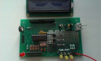
Because I wanted to build a timer with a microcontroller and an LCD-display and because this was the third project in a couple of months with the same basic components, I decided to create a prototype board for this purpose.
On the PCB all components which are basically needed can be mounted and there is a prototyping area for the rest of the circuit.
On the PCB all components which are basically needed can be mounted and there is a prototyping area for the rest of the circuit.
- - Most 18 pins PIC16 microcontrollers can be used; I normally use the PIC16F628a.
- - LCD's to be used are based on HD44780 or equivalent and have a 16 pin SIL-connector.
- - There is a small power-suply because the designs have to be operated on 9 or 12 V. Only a few mA are available for the circuit on the prototyping area. Otherwise cooling of the 78L05 or a larger stabiliser is needed. This is also the case with a larger input voltage.
- - On X1 a LED and 6 switches can be connected (to port B), X2 is connected to the prototyping area.
- - All 8 pins of port A have resistors to ground (RN1 and RN2). Eventually these resistors can be omitted if not needed.
- - You can mount a crystal with 2 capacitors if needed.
- - There is an ICSP-connector to program the microcontroller in circuit. I later realised that a jumper to switch the Vdd of the microcontroller between the ICSP-connector and power supply might be needed.
Discussie (2 opmerking(en))

magicChristian 6 jaar geleden
I like your work because I have done similar some years ago.
Why you use an old fashioned 16F628? New PIC Variants have nomore 18 but 20 pins!
And the enhanced 16Fxx have real improvements: instruction set, register saving at interrupt, higher frequency possible and lower cost.
The Arduino world uses often an interface from IIC bus to LCD 14/16 pin connector. You could add a connector for IIC on your board.
2 suggestions to the layout: set a supply cap also at LCD pins and put C4 as close to PIC as possible.
Please dont worry this a just my thoughts when looking at your project.
Antwoord
Toon meer
0 Opmerking(en)

Updates van de auteur
robvh 5 jaar geleden
The display protrudes from the PCB and there are no mounting holes.
Therefore I designed a new version for 4x20 displays which can also be used for 2x16 displays.
The size of the PCB is equal to the size of the display and the mounting holes are at the same positions.
The only electronic addition is a transistor to switch the backlight. If not needed the E and C can be connected or a jumper as shown in the photo can be used.
Board and schematic in Eagle (50kb)
Component placement (42kb)
Schematic (21kb)
robvh 6 jaar geleden
- no more solder mask in the prototype area. It's a lot easier to make solder joints between the pads.
- all pins of the B-port can be connected to connector X1 through resistors, wires or diodes.
- the E(nable) signal of the LCD-display can be connected to B0 (Int), B3 (PWM) or A1 by DIP-switches or jumper. Don't forget to close one (and only one).
- the R/W signal of the LCD-display can be connected to B1 (RX), A2 or Gnd by DIP-switches or jumper.
- The RS signal of the LCD-display can be connected to B2 (TX) or A3 by DIP-switches or jumper.
- a jumper is added between the microcontroller and the +5V power supply. This jumper can be opened during programming. For normal operation it should be closed.
- added resistor R9. You can select a crystal oscillator (install Q1, C1 and C2), an RC oscillator (install C1 and R9) or an ER oscillator (install R9 and use the second mounting hole).
- shifted the position of the LCD a little bit to have a mounting hole in the raster of the prototype area. Besides the holes now are diameter 3 mm.
remark: only install network RN2 if you are using the internal oscillator of the PICDrawings are ready, but PCB must now be ordered for test.