

Quasi-Analog Clockwork MkII [250189]
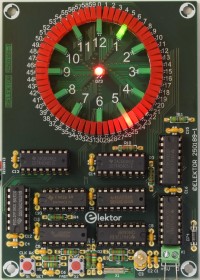
Based on the remake (2024) of classic circuit Quasi-Analogue Clockwork (1995) this MkII version has only 73 LEDs, one minute resolution, a second pushbutton to set the clock faster and the PCB is considerably smaller (80 x 113 mm). Like its predecessors only standard logic is used.
The circuit of the remake (project 240118) is adapted to have 60 red LEDs in a circle display the minutes and 12 green LEDs in an inner circle display the hours, instead of 144 round 3 mm LEDs in one circle. By using flat 2 x 5 mm flangeless LEDs for the minutes and hours they can be placed in a really small circle. The outside diameter of the red LEDs is less then 52 mm. 14-stage binary ripple counter with oscillator IC1, a CD4060, is the 32768 Hz reference oscillator and first divider. The 2 Hz output of IC1 is used as a clock signal for 12-stage binary ripple counter IC2, a 74HC4040. This counter is used to create a pulse every minute (output IC3A). This 1-minute pulse is the clock signal for 7-stage binary ripple counter IC5, a 74HC4024, which produces a pulse every hour(output IC3B). The 1-hour pulse is the clock signal for two 74HC4017, a 5-stage Johnson counter with 10 decoded outputs. 12 outputs each drive a green LED.
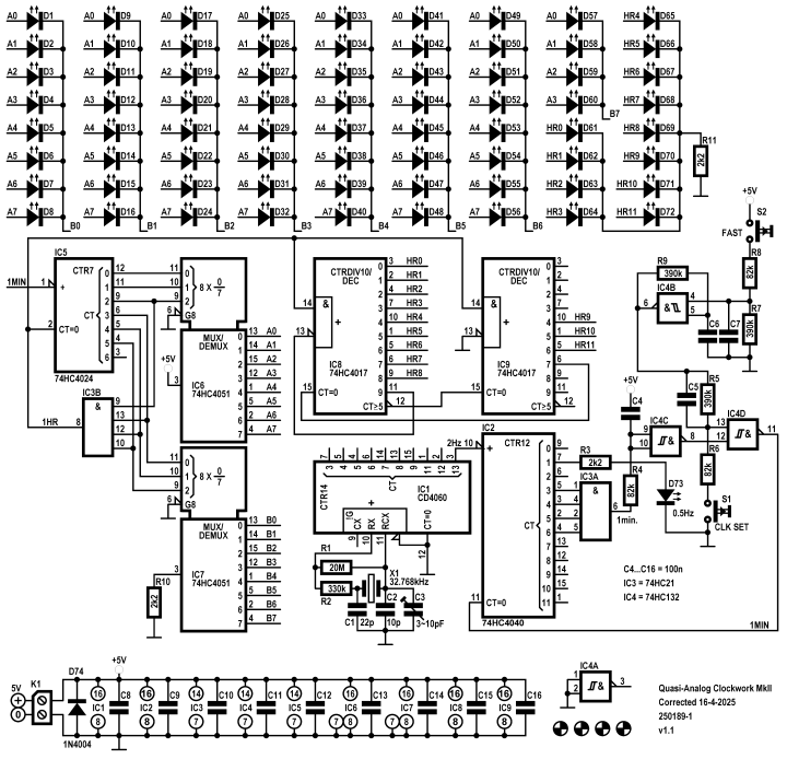
Fig. 1 Schematic of Quasi-Analog Clockwork MkII (250189-1 v1.1)
IC1 is the reference clock. Its oscillator section uses a 32768 Hz resonator in a pierce oscillator configuration. Trimmer C3 can adjust the frequency. To check the reference clock frequency easiest is to measure the 8 Hz frequency at the CT11 output (pin 1). The frequency should be exactly 8 Hz, within a few ppm. The crystal used has a tolerance of ± 20 ppm (type X32K768L104 from AEL Crystals).
IC3A resets IC2 to divide its clock input by 120, equals 8 + 16 + 32 + 64. When outputs CT3 and CT4 and CT5 and CT6 are high the output of IC3A is high and IC2 is reset via IC4C and IC4D. This creates the 1-minute pulse. The clock can be set by pushing S1, this results in an additional reset pulse through debounce network R6/R5/C5. The Schmitt-trigger input of IC4D prevents glitches. Since IC4 is a NAND an additional inverter is needed for the output of IC3A pass through to the reset un-inverted, hence IC4C.
The number of pulses to set the clock to the correct time after power-up is minimal 0 and maximal 719. This high number is not very user friendly, if S1 were the only way to set the clock. A second push button S2 activates oscillator IC4B. Its output drives the debounce network of IC4D. When the oscillator is not running this output is high, the output of IC4D is low and S1 can be used. The frequency is about 30 Hz in our prototype, but depends on the Schmitt-trigger window. It has a high tolerance, it can vary more than a factor 3. Changing full 12 hours takes 24 seconds in our prototype. If a different speed is desired change R9, a lower value will make setting the clock go faster. Use S1 to set the final minutes.
The circuit around IC5 works the same as the one around IC2. To create a 1-hour pulse IC5 must divide the 1 minute pulse at the clock input by 60, equals 4 + 8 +16 + 32. When outputs CT2 and CT3 and CT4 and CT5 are high the output of IC3B is momentarily high, IC5 is reset, creating the 1-hour pulse. Counting 1 hour starts over.
The first 6 outputs of IC5 drive analog switches IC6 and IC7, type 74 HC4051 (8-channel analog multiplexer/demultiplexer). The 8 independent inputs/outputs of IC6 are connected to the anodes of the LEDs in 8 groups of 8 (signals A0 to A7). The 8 independent inputs/outputs of IC7 are connected to the common cathodes of the beforementioned groups of 8 LEDs (signals B0 to B7). The common input/output of IC6 is connected to the +5 V power supply and the common input/output of IC7 is connected via R10 to ground. R10 sets the current of the red LEDs. In this 8 x 8 matrix only one LED is active at the time. The 3 LSB outputs of IC5 (CT0, CT1 and CT2) drive the three digital select inputs of IC6 and the next three outputs of IC5 (CT3, CT4 and CT5) drive the three digital select inputs of IC7. When IC5 is reset LED D1 is lights up, indicating 0 minutes. When IC5 has counted to 59 LED D60 lights up, indicating 59 minutes.
The 1-hour pulse is the clock signal for IC8 and IC9. Only a single output of a 4017 is active at the time (1 of 10). The active low carry output (pin12) of IC8 is used to suppress the first five counts of IC9. Output 1 (HR6) of IC9 is active when output 6 of IC8 is active. Outputs 4, 5 and 6 of IC9 are signals HR9, HR10 and HR11 respectively. Output 9 of IC8 is connected to the active low clock input (pin 13, high-to-low edge-triggered) to prevent counting any further until output 7 of IC9 resets IC8. IC9 is then immediately reset by IC8. Each of the 12 outputs of IC8 and IC9 drives a single green LED. Output 0 of IC8 is active at 12 o’clock (LED D61).
A small note about the seconds indicator LED D73. In the original design of 1995 its counter part D163 was flashing at quite a different frequency: 50 Hz/28 ≈ 0.195 Hz. Like its predecessor from 2024, LED D73 is flashing at a frequency of exactly 0.5 Hz, so 1 second on and 1 second off.
PCB
The design of the PCB is focused on smaller size (80 x 113 mm), despite the 9 ICs. To reduce a parasitic capacitance between the ground plane and the crystal there’s a void in the ground plane where the crystal is. In its predecessor this was the most likely cause of the oscillator of IC1 not starting at power-up when the crystal was placed flat against the PCB. The leads of the crystal are very thin, consider a small amount of glue to fix X1 to the PCB. Depending on how the PCB is placed inside an enclosure or in a stand screw terminal block K1 for the 5 V power supply can also be mounted on the back. Text 0 and +5 V are also placed on the bottom. D74, a 1N4004, is placed next to K1 and protects the circuit against wrong polarity. When placing IC sockets and ICs look closely at the correct orientation, especially IC1. It’s turned 180 degrees compared to the other ICs!
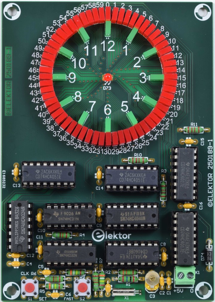
Fig. 2 Quasi-Analog Clockwork. All parts mounted (PCB 250189-1 v1.0)
Construction
Start with placing the lowest components first:
All resistors
Diode D74 (1N4004)
All IC sockets (observe correct orientation of IC1!)
Capacitors
Switches S1 and S2
LEDs D1…D60 (2 x 5 mm, red)
LEDs D61…D72 (2 x 5 mm, green)
LED D73 (3 mm, round)
Trimmer capacitor C3
Screw terminal block K1
32768 Hz Crystal X1
Fitting and soldering of the LEDs
Fig. 1 Schematic of Quasi-Analog Clockwork MkII (250189-1 v1.1)
IC1 is the reference clock. Its oscillator section uses a 32768 Hz resonator in a pierce oscillator configuration. Trimmer C3 can adjust the frequency. To check the reference clock frequency easiest is to measure the 8 Hz frequency at the CT11 output (pin 1). The frequency should be exactly 8 Hz, within a few ppm. The crystal used has a tolerance of ± 20 ppm (type X32K768L104 from AEL Crystals).
IC3A resets IC2 to divide its clock input by 120, equals 8 + 16 + 32 + 64. When outputs CT3 and CT4 and CT5 and CT6 are high the output of IC3A is high and IC2 is reset via IC4C and IC4D. This creates the 1-minute pulse. The clock can be set by pushing S1, this results in an additional reset pulse through debounce network R6/R5/C5. The Schmitt-trigger input of IC4D prevents glitches. Since IC4 is a NAND an additional inverter is needed for the output of IC3A pass through to the reset un-inverted, hence IC4C.
The number of pulses to set the clock to the correct time after power-up is minimal 0 and maximal 719. This high number is not very user friendly, if S1 were the only way to set the clock. A second push button S2 activates oscillator IC4B. Its output drives the debounce network of IC4D. When the oscillator is not running this output is high, the output of IC4D is low and S1 can be used. The frequency is about 30 Hz in our prototype, but depends on the Schmitt-trigger window. It has a high tolerance, it can vary more than a factor 3. Changing full 12 hours takes 24 seconds in our prototype. If a different speed is desired change R9, a lower value will make setting the clock go faster. Use S1 to set the final minutes.
The circuit around IC5 works the same as the one around IC2. To create a 1-hour pulse IC5 must divide the 1 minute pulse at the clock input by 60, equals 4 + 8 +16 + 32. When outputs CT2 and CT3 and CT4 and CT5 are high the output of IC3B is momentarily high, IC5 is reset, creating the 1-hour pulse. Counting 1 hour starts over.
The first 6 outputs of IC5 drive analog switches IC6 and IC7, type 74 HC4051 (8-channel analog multiplexer/demultiplexer). The 8 independent inputs/outputs of IC6 are connected to the anodes of the LEDs in 8 groups of 8 (signals A0 to A7). The 8 independent inputs/outputs of IC7 are connected to the common cathodes of the beforementioned groups of 8 LEDs (signals B0 to B7). The common input/output of IC6 is connected to the +5 V power supply and the common input/output of IC7 is connected via R10 to ground. R10 sets the current of the red LEDs. In this 8 x 8 matrix only one LED is active at the time. The 3 LSB outputs of IC5 (CT0, CT1 and CT2) drive the three digital select inputs of IC6 and the next three outputs of IC5 (CT3, CT4 and CT5) drive the three digital select inputs of IC7. When IC5 is reset LED D1 is lights up, indicating 0 minutes. When IC5 has counted to 59 LED D60 lights up, indicating 59 minutes.
The 1-hour pulse is the clock signal for IC8 and IC9. Only a single output of a 4017 is active at the time (1 of 10). The active low carry output (pin12) of IC8 is used to suppress the first five counts of IC9. Output 1 (HR6) of IC9 is active when output 6 of IC8 is active. Outputs 4, 5 and 6 of IC9 are signals HR9, HR10 and HR11 respectively. Output 9 of IC8 is connected to the active low clock input (pin 13, high-to-low edge-triggered) to prevent counting any further until output 7 of IC9 resets IC8. IC9 is then immediately reset by IC8. Each of the 12 outputs of IC8 and IC9 drives a single green LED. Output 0 of IC8 is active at 12 o’clock (LED D61).
A small note about the seconds indicator LED D73. In the original design of 1995 its counter part D163 was flashing at quite a different frequency: 50 Hz/28 ≈ 0.195 Hz. Like its predecessor from 2024, LED D73 is flashing at a frequency of exactly 0.5 Hz, so 1 second on and 1 second off.
PCB
The design of the PCB is focused on smaller size (80 x 113 mm), despite the 9 ICs. To reduce a parasitic capacitance between the ground plane and the crystal there’s a void in the ground plane where the crystal is. In its predecessor this was the most likely cause of the oscillator of IC1 not starting at power-up when the crystal was placed flat against the PCB. The leads of the crystal are very thin, consider a small amount of glue to fix X1 to the PCB. Depending on how the PCB is placed inside an enclosure or in a stand screw terminal block K1 for the 5 V power supply can also be mounted on the back. Text 0 and +5 V are also placed on the bottom. D74, a 1N4004, is placed next to K1 and protects the circuit against wrong polarity. When placing IC sockets and ICs look closely at the correct orientation, especially IC1. It’s turned 180 degrees compared to the other ICs!
Fig. 2 Quasi-Analog Clockwork. All parts mounted (PCB 250189-1 v1.0)
Construction
Start with placing the lowest components first:
All resistors
Diode D74 (1N4004)
All IC sockets (observe correct orientation of IC1!)
Capacitors
Switches S1 and S2
LEDs D1…D60 (2 x 5 mm, red)
LEDs D61…D72 (2 x 5 mm, green)
LED D73 (3 mm, round)
Trimmer capacitor C3
Screw terminal block K1
32768 Hz Crystal X1
Fitting and soldering of the LEDs
Place the cathode (short lead) of red LEDs D1…D60 outward!
Solder one lead of all the red LEDs while pushing each lead to shift the led outward. Keep the LED perpendicular to the PCB. The holes are a little bigger than the diameter of the leads. After soldering look if the LEDs line up perfectly and are equally spaced. Correct the ones that are not. Than solder the other 60 leads. The pads of the rectangular LEDs are small and thinner solder, like 0.35 mm, is advised to be used here.
Place the cathode (short lead) of green LEDs D61…D70 inward!
Perform the same handling as described for the red LEDs. Solder one lead of all the green LEDs and check if they are placed correctly. Then solder the other leads.
To even the brightness of the red and green LEDs the current through the green LEDs was increased to 6 mA by lowering the value of R11 from 2.2 kΩ to 470 Ω. Depending on the series used for the LEDs you may want to change this value. The current of the red LEDs is set by R10 and is about 1.4 mA.
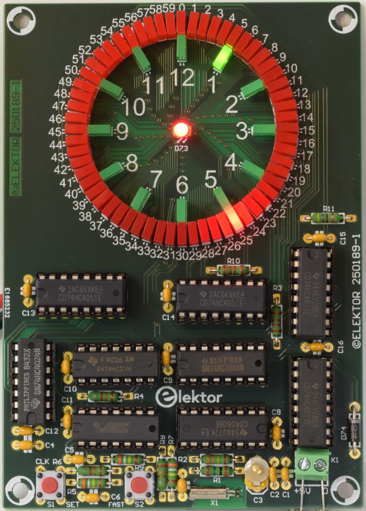
Fig. 3 Time is 1:25 (PCB 250189-1 v1.0)
Properties
Supply voltage 5 V
Supply current < 10 mA
Time display 60 minutes in a circle, 12 hours in 2nd inner circle
Display minutes 60 red 2 x 5 mm flangeless LEDs
Display hours 12 green 2 x 5 mm flangeless LEDs
Seconds indication 0.5 Hz blinking LED in center
Resolution (display) 1 minute
Technology 8 pcs HC-logic series ICs, 1 pc. 4000-logic series IC
Reference signal 32.768 kHz quartz oscillator, adjustable
Set clock 2 pushbuttons, 1 minutes step and oscillator for faster setting
Programming needed no
Bill of Materials
Resistor
R1 = 20 MΩ, 250 mW, 2.5 x 6.8 mm
R2 = 330 kΩ, 250 mW, 2.5 x 6.8 mm
R3, R10 = 2.2 kΩ, 250 mW, 2.5 x 6.8 mm
R4, R6, R8 = 82 kΩ, 250 mW, 2.5 x 6.8 mm
R5, R7, R9 = 390 kΩ, 250 mW, 2.5 x 6.8 mm
R11 = 470 Ω, 250 mW, 2.5 x 6.8 mm
Capacitor
C1 = 22p, 50 V, 5 %, ceramic, C0G/NP0, lead spacing 5 mm
C2 = 10p, 50 V, 5 %, ceramic, C0G/NP0, lead spacing 5 mm
C3 = 3~10pF, trimmer capacitor,150 V, through hole, BFC280823109 Vishay / BCcomponents
C4 - C16 = 100n, 50 V, ceramic X7R, lead spacing 5 mm
Semiconductor
D1-D60 = LED, red, 2 x 5 mm, flangeless 18 mcd @ 20 mA
D61-D72 = LED, green, 2 x 5 mm, flangeless, 18 mcd @ 20 mA
D73 = LED, super red, 3 mm (T-1), 20 mcd @ 20 mA
D74 = 1N4004, DO-41 (DO-204AL)
IC1 = CD4060, DIP-16
IC2 = 74HC4040, DIP-16
IC3 = 74HC21, DIP-14
IC4 = 74HC132, DIP-14
IC5 = 74HC4024, DIP-14
IC6, IC7 = 74HC4051, DIP-16
IC8, IC9 = 74HC4017, DIP-16
Other
K1 = 2way wire-to-board terminal block, pitch 3.5 mm
S1, S2 = 6 mm tactile push button
X1 = 32.768 kHz crystal, 20 ppm, Cload 12.5 pF, 8 x 3 mm cylinder package
X32K768L104 AEL Crystals
IC1, IC2, IC6, IC7, IC8, IC9 = IC socket, DIP, 16 contacts
IC3, IC4, IC5 = IC socket, DIP, 14 contacts
Misc.
PCB 250189-1 v1.1
Web Links
https://www.elektormagazine.com/magazine/elektor-199501/33259
https://www.elektormagazine.com/magazine/elektor-409/63743
https://www.elektormagazine.com/labs/quasi-analog-clockwork-an-elektor-classic-a-remake
PCB 250189-1 v1.1
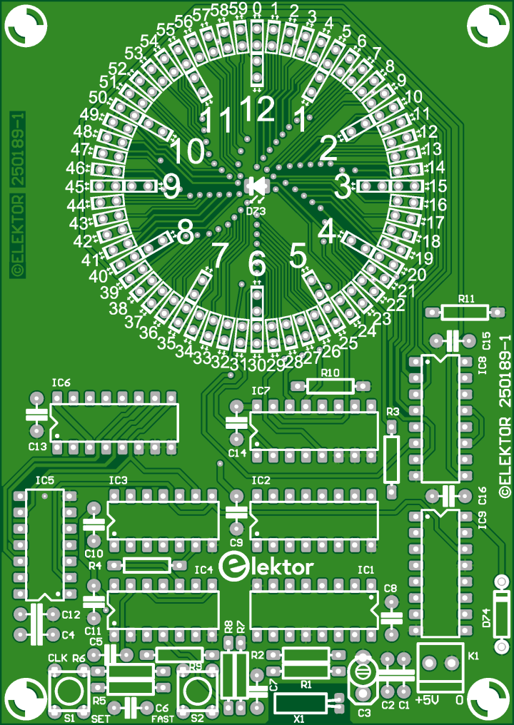
Fig. 4 Top overlay of PCB 250189-1 v1.1
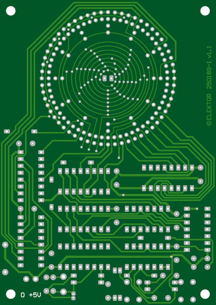
Fig. 5 Bottom overlay of PCB 250189-1 v1.1
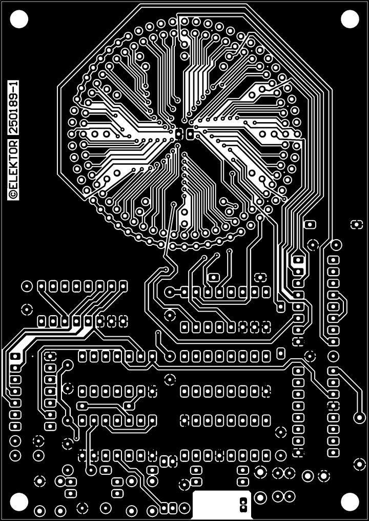
Fig. 6 Copper top of PCB 250189-1 v1.1
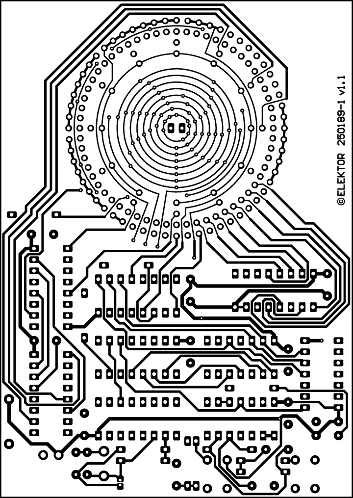
Fig. 7 Copper bottom of PCB 250189-1 v1.1
Solder one lead of all the red LEDs while pushing each lead to shift the led outward. Keep the LED perpendicular to the PCB. The holes are a little bigger than the diameter of the leads. After soldering look if the LEDs line up perfectly and are equally spaced. Correct the ones that are not. Than solder the other 60 leads. The pads of the rectangular LEDs are small and thinner solder, like 0.35 mm, is advised to be used here.
Place the cathode (short lead) of green LEDs D61…D70 inward!
Perform the same handling as described for the red LEDs. Solder one lead of all the green LEDs and check if they are placed correctly. Then solder the other leads.
To even the brightness of the red and green LEDs the current through the green LEDs was increased to 6 mA by lowering the value of R11 from 2.2 kΩ to 470 Ω. Depending on the series used for the LEDs you may want to change this value. The current of the red LEDs is set by R10 and is about 1.4 mA.
Fig. 3 Time is 1:25 (PCB 250189-1 v1.0)
Properties
Supply voltage 5 V
Supply current < 10 mA
Time display 60 minutes in a circle, 12 hours in 2nd inner circle
Display minutes 60 red 2 x 5 mm flangeless LEDs
Display hours 12 green 2 x 5 mm flangeless LEDs
Seconds indication 0.5 Hz blinking LED in center
Resolution (display) 1 minute
Technology 8 pcs HC-logic series ICs, 1 pc. 4000-logic series IC
Reference signal 32.768 kHz quartz oscillator, adjustable
Set clock 2 pushbuttons, 1 minutes step and oscillator for faster setting
Programming needed no
Bill of Materials
Resistor
R1 = 20 MΩ, 250 mW, 2.5 x 6.8 mm
R2 = 330 kΩ, 250 mW, 2.5 x 6.8 mm
R3, R10 = 2.2 kΩ, 250 mW, 2.5 x 6.8 mm
R4, R6, R8 = 82 kΩ, 250 mW, 2.5 x 6.8 mm
R5, R7, R9 = 390 kΩ, 250 mW, 2.5 x 6.8 mm
R11 = 470 Ω, 250 mW, 2.5 x 6.8 mm
Capacitor
C1 = 22p, 50 V, 5 %, ceramic, C0G/NP0, lead spacing 5 mm
C2 = 10p, 50 V, 5 %, ceramic, C0G/NP0, lead spacing 5 mm
C3 = 3~10pF, trimmer capacitor,150 V, through hole, BFC280823109 Vishay / BCcomponents
C4 - C16 = 100n, 50 V, ceramic X7R, lead spacing 5 mm
Semiconductor
D1-D60 = LED, red, 2 x 5 mm, flangeless 18 mcd @ 20 mA
D61-D72 = LED, green, 2 x 5 mm, flangeless, 18 mcd @ 20 mA
D73 = LED, super red, 3 mm (T-1), 20 mcd @ 20 mA
D74 = 1N4004, DO-41 (DO-204AL)
IC1 = CD4060, DIP-16
IC2 = 74HC4040, DIP-16
IC3 = 74HC21, DIP-14
IC4 = 74HC132, DIP-14
IC5 = 74HC4024, DIP-14
IC6, IC7 = 74HC4051, DIP-16
IC8, IC9 = 74HC4017, DIP-16
Other
K1 = 2way wire-to-board terminal block, pitch 3.5 mm
S1, S2 = 6 mm tactile push button
X1 = 32.768 kHz crystal, 20 ppm, Cload 12.5 pF, 8 x 3 mm cylinder package
X32K768L104 AEL Crystals
IC1, IC2, IC6, IC7, IC8, IC9 = IC socket, DIP, 16 contacts
IC3, IC4, IC5 = IC socket, DIP, 14 contacts
Misc.
PCB 250189-1 v1.1
Web Links
https://www.elektormagazine.com/magazine/elektor-199501/33259
https://www.elektormagazine.com/magazine/elektor-409/63743
https://www.elektormagazine.com/labs/quasi-analog-clockwork-an-elektor-classic-a-remake
PCB 250189-1 v1.1
Fig. 4 Top overlay of PCB 250189-1 v1.1
Fig. 5 Bottom overlay of PCB 250189-1 v1.1
Fig. 6 Copper top of PCB 250189-1 v1.1
Fig. 7 Copper bottom of PCB 250189-1 v1.1
Discussie (0 opmerking(en))