Raspberry Pi Battery Power Supply With Safe Shutdown
Here is a possible solution to power portable devices based on Raspberry Pi. The goal of this project is to propose a power supply system using a rechargeable battery for portable devices, including those in a "headless" configuration (i.e. without a monitor, keyboard, and mouse) that can safely shut down the operating system when the device is turned off. The circuit described in the article can also be used as a UPS (Uninterruptible Power Supply) or Power Bank.
From Idea to Realization
Experimenting with the Raspberry Pi, one might suspect that the designers of these boards have somewhat neglected the aspect of power management (perhaps intentionally, to keep costs down), at least until the arrival of version 5. As soon as the USB connector is plugged in, the microprocessor starts loading the Operating System. After using the device, to reduce the power consumption to zero, it is necessary to disconnect the power cable. In fact, depending on the type of card, configuration and peripherals connected, there still remains a power consumption that can vary from a few tens to a few hundred mA (milliamperes). There is also a real risk of corrupting the Operating System residing in the microSD if the power is cut before the file system has been properly "unmounted".
That the problem is real is evidenced by the number of accessories on the market designed to improve and simplify power management. They range from the rudimentary USB cable with a pass-through switch (!) to dedicated HATs (Hardware Attached on Top), the latter being add-on boards to be plugged onto the forty-pin GPIO connector, often equipped with a microcontroller and sometimes batteries, and generally requiring the installation of special software (scripts) to perform their function. From such considerations, the idea was born to design a custom solution, using readily available components and with some specific features, such as power supply with a rechargeable battery, power on with a button, power off with a long press of the same button with safe shutdown of the Operating System and subsequent full automatic power off, safe automatic power off with low battery, no scripts to install. In the course of this article, we will see if and how these goals were achieved, starting with an analysis of the schematic.
Schematic Diagram
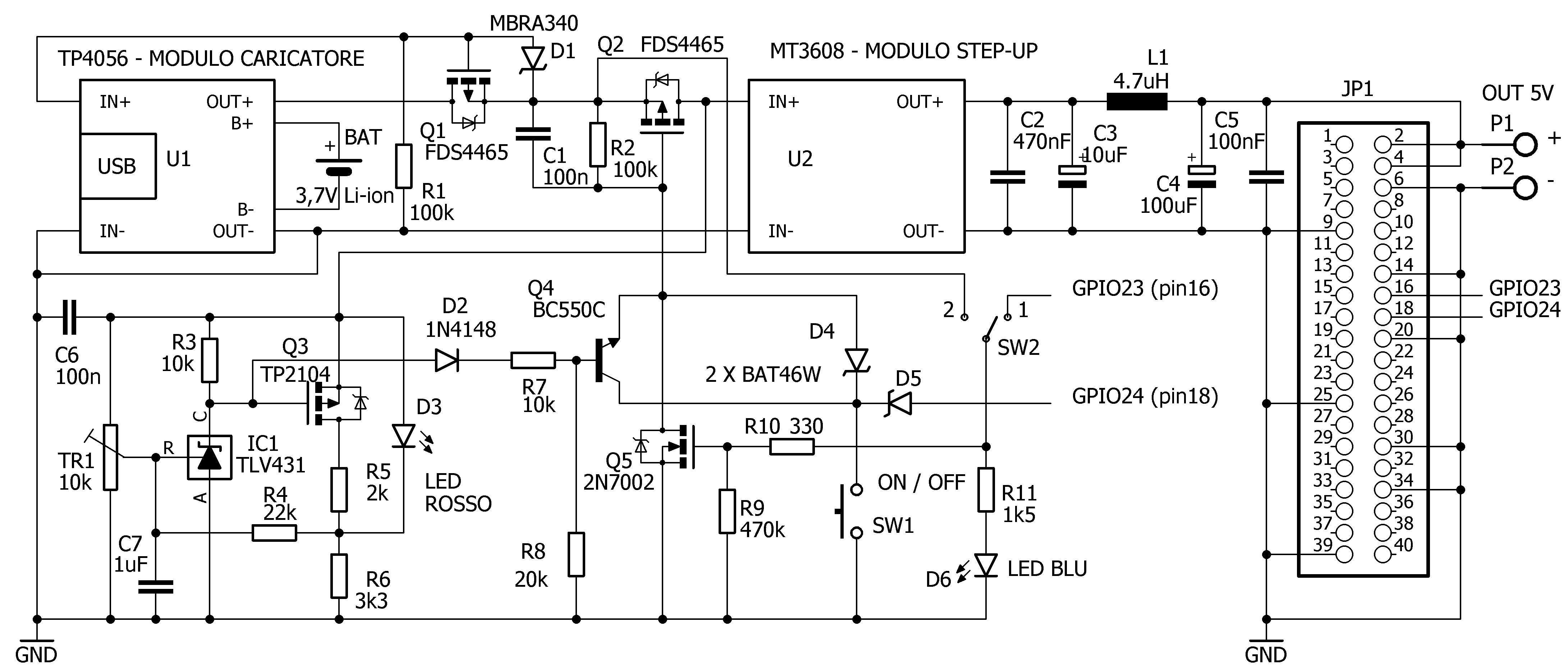
The power supply schematic is shown in Figure 1. The power source is an 18650 Li-ion battery connected to an inexpensive and readily available charger module with protection circuitry, equipped with the TP4056 chip. Choosing the module with protection is mandatory, as most 18650 batteries do not have it. Raspberry Pi boards require a supply voltage of 5.1V, as clearly stated in the official documentation of the manufacturer [1], along with many other very useful information. So the first step is to get this voltage from the nominal 3.7V supplied by the battery. We are helped by a step-up module (voltage booster), also widely used, based on the integrated circuit MT3608, which, according to the data sheet [2], has a maximum current capability of 2A, can operate with a minimum input voltage of 2V, and returns up to 28V in the output. Tested under real conditions and with a charged battery, the maximum available output current, with the voltage still stable at 5.1V, comes to 1A, more than enough in any case to power, for example, a Raspberry Pi Zero 2 W board, a model definitely worth considering for building compact portable devices.
A configuration with Raspberry Pi 3B, LCD display, DAC and Wi-Fi was also tested without any problems. Obviously, battery life varies with average power consumption and is very difficult to quantify precisely given the many variables involved (converter efficiency, board model, connected peripherals, use of Wi-Fi and/or Bluetooth, running processes). With a 3500mAh battery, two to five hours of runtime can be achieved, which is not bad considering the simplicity of the circuit and the low cost of the components used.
Returning to the circuit diagram and proceeding in order, let us examine the function of Q1, a P-type MOSFET. Its task is to isolate the battery from the rest of the circuit during battery charging. In this way, the TP4056 module's end-of-charge sensor can do its job properly. Otherwise, any current drawn by the load at the same time as the battery would lead to failure of the control circuit and overcharging of the battery itself. This important aspect regarding the proper charging of Li-Ion batteries, which is often underestimated, is addressed in detail in Microchip's Application Note AN1149 [3], from which the circuit section under consideration is taken. In practice, when the charger is disconnected, the battery voltage can reach the rest of the circuit through Q1, which is in conduction because the gate terminal is at a sufficient negative potential relative to the source. With the charger connected, Q1 stops conducting (positive gate potential relative to source), isolating the battery from the load, which can, if necessary, continue to receive current through diode D1.
Using a charger of adequate quality and current capacity (e.g., 2.5A at 5V) has the dual advantages of being able to recharge the battery while the device is running and of also being able to use the proposed circuit as a UPS, leaving the charger connected at all times. In the event of a power failure, the battery will provide power to the load, seamlessly.
Q2 is the real switch in the circuit; it is normally interdicted due to the presence of R2 (gate at the same potential as the source, with C1 preventing the MOSFET from conducting as soon as the battery is connected) and goes into a conducting state when the gate is brought to ground potential. This can be done in two ways, via D4 and pressing SW1 or via Q5, N-type MOSFET brought into conduction by a high logic level present on GPIO23 of the connected Raspberry Pi board. The GPIO24 pin is configured as an input with a pull-up resistor and monitors the state of the button, through D5, which prevents excessive voltage from reaching the pin itself (the maximum value for the Raspberry Pi is 3.3V).
Using two generic GPIOs on the board, it is then possible to achieve the desired operation, which I describe below. Pressing SW1 Q2 conducts, the Step-Up module powers the Raspberry Pi board, the microprocessor initializes the pins (by default at low level at startup ) bringing GPIO23 to high level, LED D6 lights up, Q5 conducts and brings Q2 into conduction. The button can then be released. To turn off the device, SW1 must be pressed and held down. Three seconds after the change of state, detected by GPIO24, the command to shut down the Operating System is given, and only when the file system has been “ unmounted” and it is safe to interrupt the power supply, GPIO23 goes to logic low, LED D6 goes out, and Q5 stops conducting. At this point the button can be released, Q2 goes into interdiction interrupting the power supply to the Raspberry Pi board and thus totally zeroing out the power consumption.
Continuing with the schematic, at the output of the Step-Up module we notice components L1, C2, C3, C4, C5, which have the function of a filter, reducing the residual noise typical of switching converters, at the level of a few millivolts, even at maximum load. For C3 and C5 I recommend elements with low ESR (Equivalent Series Resistance). Readers with more experience in the Raspberry Pi environment will have noticed that the board's power is supplied via the 5V pins (physical pins 2, 4) and the ground pins of the 40-pin header, and not via the dedicated USB connector, which must remain unused. This type of connection does not actually cause any inconvenience to the conscious user (on Type 3 Raspberry Pi boards, the fuse protecting the USB port is actually bypassed), but it does result in a small reduction in contact resistance in the current path, which improves the efficiency of the circuit. In the absence of the Raspberry Pi board, switch SW2 in position 2 allows the step-up module to be powered and the circuit to be used as a 5V power bank or portable power supply.
The last part of the circuit, built around IC1, Q3 and Q4, has the function of determining the safe shutdown of the Operating System and subsequently disconnecting the power supply, when the battery voltage falls below a certain value, set with trimmer TR1. IC1 is the low-voltage version of the more widely used TL431, classified as an adjustable-precision shunt voltage reference [4], often found in power supply circuits, especially of the switching type. In this case it is used as a voltage comparator, taking advantage of the precise 1.24V reference on the R pin. As long as the voltage on R is greater than the reference (sufficient battery charge), IC1 conducts and so does Q3 (negative gate to source), which keeps LED D3 off. Transistor Q4, which as a practical effect is connected in parallel with SW1, is interdicted. If the battery voltage falls below the threshold set with TR1, IC1 stops conducting and the voltage available on its cathode (terminal C) is sufficient to interdict Q3 (LED D3 lights up) and send Q4 into conduction, through D2 and R7. If this state persists for more than three seconds, the same effect caused by prolonged pressing of the SW1 button, described above, is obtained. The emitter of Q4 is at negative potential only if Q5 is conducting. After the power supply is interrupted (Q5 interdicted) it is actually isolated from ground. This prevents the circuit from restarting, as if SW1 were still closed. Resistor R4 introduces some hysteresis into operation (a “window” of about 100mV), to prevent unwanted activations due to short fluctuations in battery voltage. Capacitor C1 helps neutralize any noise transients, C6 is a recommended bypass for IC1 stability. R5 and R6 limit the current in the LED while D2, R7 and R8 determine the conduction threshold of Q4. To easily calibrate the circuit, one can, with TR1 turned fully toward R3 and C6 and without Raspberry Pi installed, connect a variable power supply regulated to 3.7V instead of the battery and turn on the circuit via SW2. The red LED should remain off. Then adjust the power supply for the desired threshold voltage (e.g., 3.0V) and slowly turn TR1 until D3 turns on. Then check for proper operation with Raspberry Pi installed and configured. If Q4 is of a different type or its gain is not within the parameters, it may be necessary to tweak the value of R7 or R8 to get the transistor to trip correctly.
Device Tree Overlays e config.txt
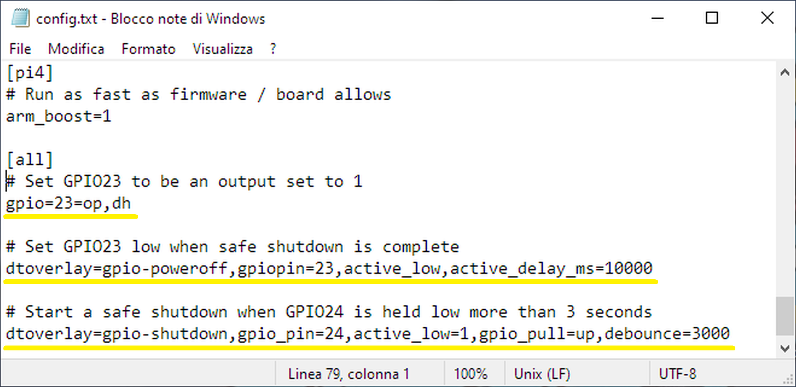
As already mentioned, circuits of this type often require the installation of a script file, typically in Python, which must be executed automatically at Operating System startup, e.g., by adding the appropriate references to the rc.local file or, better, by running the script as a system service. The script must contain all the instructions useful for configuring the GPIOs used (input or output, logic level high or low) and executing the necessary functions, such as handling the state of a button, the power switch, and sending the shutdown command to the operating system installed on the Raspberry Pi. However, it is possible to achieve the same result in a simpler and more elegant way by taking advantage of a feature of Linux family Operating Systems, that is, the use of Device Tree (DT) and Device Tree Overlays (DTOs) data structures for describing the hardware with which the Raspberry Pi OS kernel (core) is to interface [5]. Thanks to this peculiarity, it is easier to update the list of devices and drivers compatible with the OS, as well as to add new ones by the user himself. A crucial role is also played by the config.tx file, located in the “/boot/” directory. This file contains basic information about the hardware configuration of the Raspberry Pi board (interfaces, audio and video parameters, etc.), which can be modified if necessary, but it also allows the addition of extra overlays instructions, defined by the user, which will then be added to the information of the Device Tree and other Device Tree Overlays. The boot loader (the program that loads the operating system at boot time) takes care of analyzing DTs, DTOs, and config.txt files, combining their contents and then passing the necessary data to the kernel to boot the operating system with the desired hardware configuration. Simplifying as much as possible and getting to the point, it is possible, with only three lines of text, to configure the GPIO23 and GPIO24 pins, defining their behavior to meet all the needs of the project. The config.txt file (path “/boot/config.txt”) is also easily accessible and editable from Windows, simply by inserting the microSD card into any suitable reader (the same one used to write the operating system image). After the text already in the file, the following lines should then be added:
The first line sets GPIO23 to logic high at startup to allow power-on; the second line causes GPIO23 to go to logic low for 10 seconds once the operating system shutdown is complete to allow safe shutdown. The last line activates the internal pull-up resistor of GPIO24 and causes it to start the safe shutdown procedure if the same pin is held at logic low for more than 3 seconds, either by pressing the SW1 button or by the conduction state of transistor Q4. An example of how to modify the config.txt file is shown in Figure 2. Any comments, which are always useful as reminders, should be preceded by the "#" character.
Other than the additions to the config.tx file, no other changes to the Operating System are required. Functional testing was performed with the Bullseye version of Raspberry Pi OS Lite (32-bit) available at the time of writing. Documentation (README) about device tree overlays, parameters and available options can be found on GitHub [6]. The pinout can be varied if necessary, checking that it does not interfere with the configuration required by other programs running on the Raspberry Pi and modifying the wiring accordingly.
Realization of the Prototype
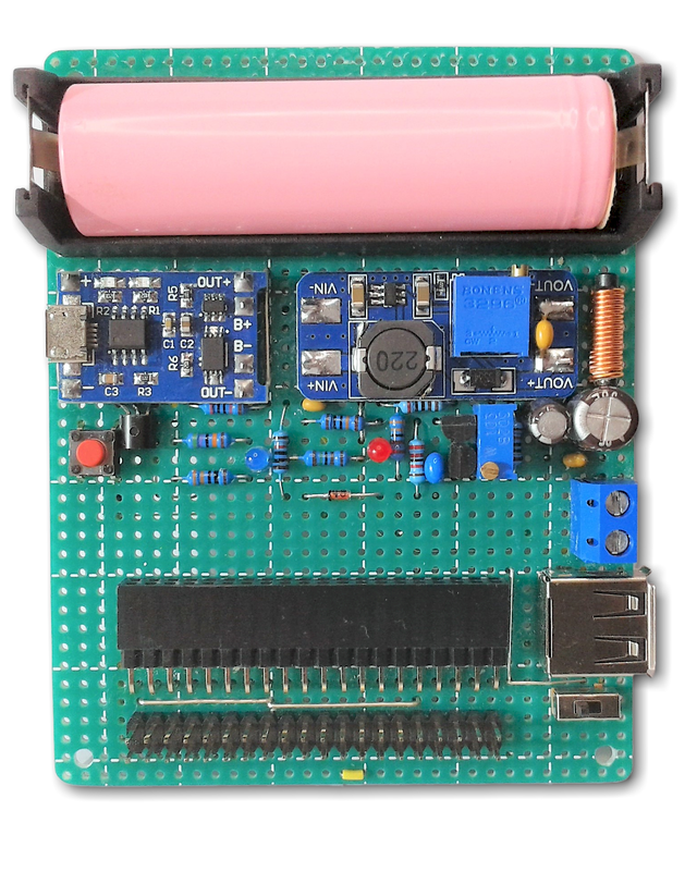
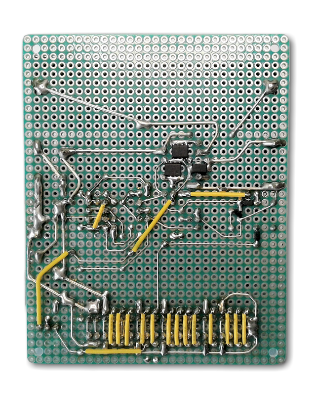
The prototype was made on a perfboard, as shown in Figure 3, and does not present any particular critical problems. The only recommendation is to make the ground path, and in general any connection through which high currents flows, with conductors of appropriate section and as short as possible to minimize voltage drops and improve the efficiency of the circuit. I used common through-hole components, except for the very low RDS(on) FDS4465 [7] MOSFETs, which are only available in SMD packages, as well as the BAT46W and MBRA340 diodes and the 2N7002 MOSFET. To accommodate the Raspberry Pi board, I used a 2 x 20 pin female connector defined as "extra tall" and manually bent the pins to allow it to be mounted at a right angle. I chose to mount the board vertically to improve airflow and heat dissipation around the board. To still have access to the forty pins, this connector was "duplicated" with a corresponding male connector that exactly matches the Raspberry Pi header and patiently made the necessary connections.The manufacturer's configuration has been followed for the ground connections. This leaves the possibility to connect additional components, expansion boards, Hats, adapters or breadboards. For the sake of simplicity, I have not shown this connector in the schematic, nor the USB type A PCB socket, which was added in expectation of use as a power bank. The bipolar screw terminal allows the output voltage to be taken from flying leads.
I recommend to adjust the output voltage (5.1V) of the MT3608 module before mounting it, using the multiturn trimmer provided, by connecting a stabilized power supply regulated to 3.7V at the input and a load at the output, in order to test the Step-Up in real working conditions. A note on the 4.7 µH L1 inductor: it should be of the type used in switching power supplies, low resistance and sized for at least 2A current to avoid excessive voltage drops. It is a good idea to solder the multilayer ceramic capacitor C2, 470nF, directly to the VOUT+ and VOUT- pads of the MT3608 module, as shown in Figure 3. I have found experimentally that this provides better suppression of residual high frequency noise, which is always possible in this type of circuit. Another option is to mount SW1, SW2 and the LEDs some distance away from the PCB, e.g. on the front panel of the eventual enclosure. Figure 4 shows the prototype from the soldering side. I also consider such a realization as an exercise to train and retain some manual abilities. Certainly a printed circuit board, perhaps double sided, would be preferable if more than one prototype of the circuit is required to be made. I have also found that the use of surface mount components on a perfboard is possible without any particular difficulty, and can bring undoubted advantages in terms of compactness and short signal paths. Finally, a useful addition to the project could be a battery charge indicator, perhaps in the form of a mini digital voltmeter or LED bar module, both of which are inexpensive and easily available.

Discussie (2 opmerking(en))