The success and popularity of Raspberry Pi boards is certainly well-deserved, but over time many users have noticed and complained about the lack of a power button.
Finally, the desired button has been added to the new Raspberry Pi 5 model, but owners of earlier models may find this project useful. Such accessories are nothing new, there are both commercial and DIY offerings, from the simple cable with a switch to the sophisticated HATs (Hardware Attached on Top). The solution I am proposing has the advantage of a rather simple wiring diagram and does not require any programming or installation of scripts or automatic startup services. A few components and the addition of three lines of text to the config.txt file make it possible to power on the Raspberry Pi board at the press of a button, shut down the operating system correctly even in headless systems, and automatically disconnect the board's power supply without having to unplug the USB connector, thus reducing the current draw to zero.
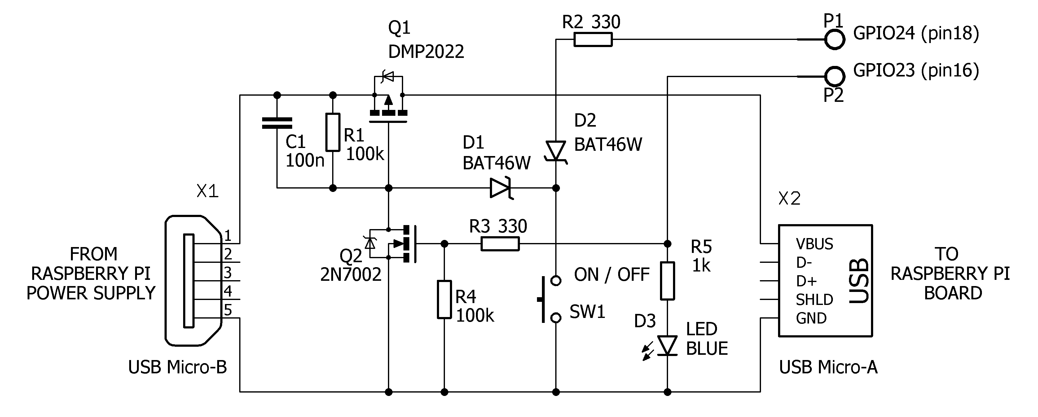
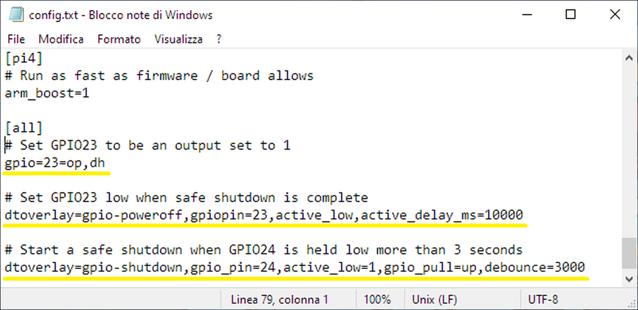
Schematic: The circuit must be interposed between the normal power supply and the Raspberry Pi board, and also connected to two free generic GPIO pins on the 40 pin connector. Before connecting the circuit, it is necessary to define the behaviour of these two pins using a feature introduced in the most recent versions of Raspberry Pi OS. This feature is known as Device Tree Overlays, which allows instructions for hardware operation to be inserted in text form into the config.txt file. This file (which is loaded at each boot of the operating system) is located in the bootfs partition of the operating system's micro SD card and is easily accessible even from Windows and can be modified using any text editor. The following three instructions must be added at the end of the file:
Start a safe shutdown when GPIO24 is held low more than 3 seconds. GPIO24 is set as an input with pullup.
An example of a modified config.txt file, including comments: At this point, the operation of the circuit becomes clearer. By pressing and holding the SW1 button, the MOSFET Q1 (P-CHANNEL) is turned on. This powers the Raspberry Pi board and boots the operating system. Within about one second GPIO23 goes high, the blue LED lights up, the MOSFET Q2 (N-CHANNEL) goes on and keeps Q1 on and the button can be released. If you now shut down Raspberry Pi from the Start menu on the OS desktop, at the end of the process (Safe Shutdown) GPIO23 will go low, the blue LED, Q1 and Q2 will turn off and the power to the board will be cut. The same effect is achieved by pressing the button for more than three seconds. After this time, GPIO24 activates the Safe Shutdown procedure without the user having to access the operating system, which is very useful in headless systems.
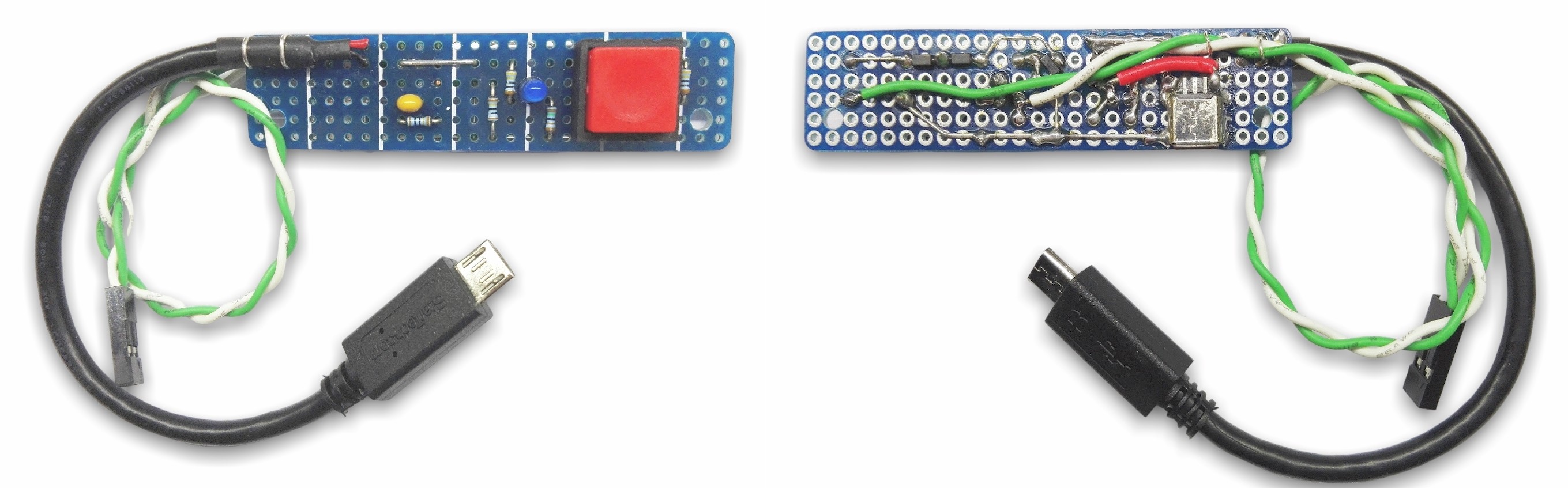
Prototype: To proceed with the schematic description, C1 and R1 prevent Q1 from turning on when the power supply is connected, D1 and D2 protect GPIO24 from the 5V voltage present at Q1's gate (via R1) when Q2 is turned off, R4 is the pulldown of Q2's gate, R2 and R3 protect the GPIOs from overcurrent. The MOSFET Q1 was chosen for its low on-resistance value, 16mΩ @ VGS = -4.5V, in order to minimise voltage drop and power loss.

Discussie (1 opmerking(en))