

Solar grid tie inverter re-engineered
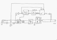
I repaired a chinese grid tie inverter for small solar systems, Input 50-100V, Output 230V 300W. The failure was in the reference voltage inside the µC ATMega8, it dropped down arbitrary. To be able to find this failure, I had to re-engineer the complete set and had to draw the schematics by my own.
I repaired a chinese grid tie inverter for small solar systems, Input 50-100V, Output 230V 300W. The failure was in the reference voltage inside the µC ATMega8, it dropped down arbitrary. To be able to find this failure, I had to re-engineer the complete set and had to draw the schematics by my own. I share this here to help other insane electrophile humans to get familiar with grid tie inverters.
Discussie (14 opmerking(en))


Heath Flicos 1 jaar geleden
I'd reverse engineered most of my 300W inverter when I stumbled across this post, which saved me some time. It looks like I had the same fault with mine as you did. I replaced the linear regulator that provides the 11V and then all worked OK again.
I wonder if it's possible to disable the MPPT function? I'd like to connect this to a battery and then control the amount of power generated however the MPPT function controls the power automatically and this will just generate max power (and probably overheat and die!).
Update:9/5/23:
The F/W is easily updated to disable the MPPT and now I am able to select the desired generation power to generate from a battery source. Code available upon request :-)
Antwoord
Heath Flicos 1 jaar geleden
I've enclosed my first test firmware as requested (written using the Arduino software, selecting the Atmega8 target). It's still very much in the early development. There is Anti Islanding but no measurement of the NTC or current.
For testing purposes I hard coded the selected output power which enabled me to prove the concept. I probably won't enhance this code any further because the input voltage range is rather restricted and requires a Buck Converter between the battery and the GTI to get the voltage into range.
The schematics have already been shared by the originator of this pose (mine was exactly the same) however I see that your GTI is different, so you will need to trace out the schematic for yourself (there may be some similarities) .
Antwoord

max77ro 1 jaar geleden
I'm interested in the firmware you modified , schematics also if you could share
I used mine connected to a battery and as you said it overheated and blowed a mosfet
I replaced the mosfet and tested with a small voltage, worked as expected ( injecting in the grid )
Sadly when I used it with the main battery something else blew (there was a fain pop sound ) , and I cannot seem to find what
Now it just lights the fault LED after the initial check
Thanks in advance ,
Marius
Antwoord
Toon meer
2 Opmerking(en)


mariano.andre 4 jaar geleden
Saudações Pter!
Eu trabalho com consertos eletrônicos e gostaria de ver o esquema eletrônico que você redesenhou, no entanto, não consegui acessar as imagens nem o esquema. Por favor, você poderia compartilhar o link de acesso aos arquivos?
Desde já agradeço sua atenção e disposição.
Grande abraço.
Mariano Anderson
Brazil
Antwoord
Toon meer
0 Opmerking(en)


jonr 7 jaar geleden
Nice work! Did you have any idea if this exact device is still available anywhere (eg on ebay)? Would be interesting to load some alternate firmware on it.
If I understand it correctly, the H-bridge uses the grid to control the gates and determine if it inverts or not?
If I understand it correctly, the H-bridge uses the grid to control the gates and determine if it inverts or not?
Antwoord
Toon meer
0 Opmerking(en)

Minga Vasile 8 jaar geleden
Congratulations for your hard work! My chinese grid-tie inverter, model TEG-500W-WAL, 10.8-30V input with uP ATMEGA88PA was defective. uP pins 30 and 31 was placed in to the ground. Pin 30 coupling main relay bar + (after few seconds from the start). The inverter works fine with contact relay put in brief, but uP heated . I have not found anyone to burn fusible and read the content. Can I use hex file provided by you to rebuild inverter with all the parts and ATmega8, or need to rebuild transformers?
best regards
best regards
Antwoord
Toon meer
1 Bijlage(n)
0 Opmerking(en)


greenlicium 9 jaar geleden
and moreover to share your experience with us!
do you mind it's possible to package all your draft into a single zip file in order to facilitate the download.
Is it also possible to have the exact part number of the item are at least a good photo?
regards.
Antwoord
Toon meer
0 Opmerking(en)
Updates van de auteur
Pter 9 jaar geleden
bram ...... adisakti 7 jaar geleden
Sivuca 5 jaar geleden
Good job,
My 600W solar inverter lives by burning power MOSFETs after a first firing with lightning. With your scheme, now I'll try to check the sync.
Thank you!