

Timer for bathroom ventilation
Use a microcontroller to get a simpler and more stable timer.
The idea
A replacement was needed for a burned timer, which switches on the fan if the light is switched on and switches it off some time after the light has been switched off. The original PCB contained a cmos chip (MC40106), a big electrolyt (100uF) and a big resistor (1M + 10M potmeter) for the timing.
In my new version I wanted an additional timer: the fan will be switched on some time after the light is on to prevent a running fan if someone just looks in the mirror for a few seconds. This would require a second RC-network and a more complicated circuit.
Using a microcontroller can make things a lot simpler. But I wanted to keep one feature of the old timer: the potmeter(s) to set the timing.
Hardware
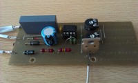
The new circuit contains a small PIC microcontroller, which consumes only 400 uA at 500 kHz clock frequency. For the setting of the timers, 2 potmeters are connected to analog inputs. Because they are used as voltage dividers their value is not critical. The only big capacitor is in the power-supply, which consist of only a few parts. A series capacitor is used to limit the current (use an X2-capacitor for this purpose!) and a zener diode determines the voltage. Further a circuit is needed to determine if the light is on. This is done by a diode and a resistor (use at least 2 in series because of the voltage). In my timer I used a TIC206 triac, but if only a small fan has to be driven you can use the TO92 version (TICP206), which is much smaller.
Software
The program contains an interrupt routine which is called ~256 times each minute or once each 234 ms. If no pulse from the lamp circuit is received during this period of time, the lamp is considered to be off.
The main loop of the program is a simple state machine; more information can be found in the source code.
In the EEPROM of the PIC 2 numbers are stored: the max. number of minutes delay (default 5) and the max. number of minutes run time (default 15). With the potmeters the timers can be set between 0 (zero) and the max. number of minutes. And because of the principle used, the potmeters have a linear scale, which makes it easy to estimate the time set.
The program is compiled by CC5X of B. Knudsen, but porting to another compiler should not be too complicated.
A replacement was needed for a burned timer, which switches on the fan if the light is switched on and switches it off some time after the light has been switched off. The original PCB contained a cmos chip (MC40106), a big electrolyt (100uF) and a big resistor (1M + 10M potmeter) for the timing.
In my new version I wanted an additional timer: the fan will be switched on some time after the light is on to prevent a running fan if someone just looks in the mirror for a few seconds. This would require a second RC-network and a more complicated circuit.
Using a microcontroller can make things a lot simpler. But I wanted to keep one feature of the old timer: the potmeter(s) to set the timing.
Hardware
The new circuit contains a small PIC microcontroller, which consumes only 400 uA at 500 kHz clock frequency. For the setting of the timers, 2 potmeters are connected to analog inputs. Because they are used as voltage dividers their value is not critical. The only big capacitor is in the power-supply, which consist of only a few parts. A series capacitor is used to limit the current (use an X2-capacitor for this purpose!) and a zener diode determines the voltage. Further a circuit is needed to determine if the light is on. This is done by a diode and a resistor (use at least 2 in series because of the voltage). In my timer I used a TIC206 triac, but if only a small fan has to be driven you can use the TO92 version (TICP206), which is much smaller.
Software
The program contains an interrupt routine which is called ~256 times each minute or once each 234 ms. If no pulse from the lamp circuit is received during this period of time, the lamp is considered to be off.
The main loop of the program is a simple state machine; more information can be found in the source code.
In the EEPROM of the PIC 2 numbers are stored: the max. number of minutes delay (default 5) and the max. number of minutes run time (default 15). With the potmeters the timers can be set between 0 (zero) and the max. number of minutes. And because of the principle used, the potmeters have a linear scale, which makes it easy to estimate the time set.
The program is compiled by CC5X of B. Knudsen, but porting to another compiler should not be too complicated.


Updates van de auteur
robvh 2 jaar geleden
Resistors R11, R12 and R13 cannot be replaced by a single resistor of 150k because of the high voltage. Diode D3 is needed if the opto coupler has no internal diode anti-parallel to the LED. It prevents a high reverse voltage over the LED.
If JP2 is connected the timing is loaded from the internal EEPROM of the microcontroller. In that case R3, R4, R7 and R8 are not needed. If you want to program your own timing in the EEPROM some calculation is required, because the timing is expressed in 0.528 second intervals. With R7 the delay can be set between 0 an 9 min. and with R8 the running time can be set between 3 and 30 min. If the controller is not to be programmed on the board JP3 is not needed.
The power supply can be replaced by any 12V supply that is powerfull enough to power the board (~40mA) and the fan (my fan needed 350mA).
To make the switching of the supply less critical the relais is switched on 10 seconds before the fan and switched off 10 seconds after the fan.
This version is used in my bathroom since a couple of months; although more complicated I like it more than the original one because it is not connected to mains power most of the time.
fantimer_uni.zip (5kb)
partslist.txt (1kb)
fantimer-uni1.jpg (485kb)
fantimer-uni2.jpg (2146kb)
PCB1840_bath_brd.pdf (17kb)
robvh 3 jaar geleden
C3 is 47uF/25V, but is only used for 5V, so a 47uF/10V version will also be ok
C4 is a small ceramic capacitor of 0.1uf/63V
Packages can be seen in the photograph of the prototype; in the final version the same capacitors were used.
Sven Plese 3 jaar geleden
robvh 4 jaar geleden
This might be a solution for you.
The original circuit is connected to the mains on 3 places:
1 - The power supply. This is the most obvious one. The circuit can be powered by any 5V power supply. In my test I used a suppy with a small transformer and a 7805, but an USB-charger could also do the job. Eventually capacitor C3 is needed if the time there is no primary power during switching of the contact is too long. Often it will not be needed.
2 - The triac. Isolation can be simply achieved by using a relais instead of the triac. The original power-supply with the series capacitor was not able to provide enough power for a relais.
3 - The detection of the lightswitch. In the original circuit this input is connected to the microcontroller through a series resitor. This is done to save current consumption from the 5V supply. By using an opto-isolator complete galvanic isolation is accomplished.
And last but not least: to prevent continuous connection of the circuit to the mains, a second contact of the relais is used to power the timer. Normaly the timer is connected to the lichtswitch; as soon as the fan is running it is connected to the live. Therefore if the fan is not running and the light is off, the circuit is completely switched off.
Additionally I added a faeture to the software: it autmatically recognizes the output device used; the output polarity will be inverted for a triac (as originally) or pnp-transistor, but positive for an npn-transistor,
fantimer1.zip (4kb)
fantimerx_sch.pdf (17kb)