

tiny radio [150587]
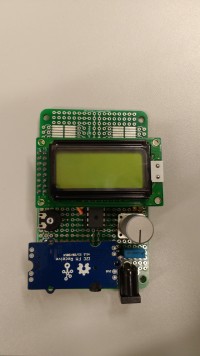
I made a simple way to use the i2c fm receiver from Seeed Studio. It uses an ATmega328p, an 8x2 character LCD display and a rotary encoder and is built on the ELPB-NG (150180). The rotary encoder is used to control the functions of the FM module in a user-friendly way. When you start the board you see the frequency you're currently listening to.
I made a simple way to use the i2c fm receiver from seeed studio. It uses an atmega328p, an 8x2 character lcd display and a rotary encoder and is built on the elpb-ng (150180). The rotary encoder is used to control the functions of the fm module in a user-friendly way. When you start the board you see the frequency you're currently listening to. The radio frequency can be changed manually or automatically. When searching automatically, the module searches up or down, depending in which direction the rotary encoder is turned, and stops when in finds a strong signal. To open the main menu, you press the rotary encoder. In this menu you can change the volume, switch between automatic and manual scanning and mute the audio. When you power off the board, the frequency, volume and other settings are saved in the EEPROM.
I also made a small, minimalistic version to use the fm receiver. This is a small board with an attiny85, two buttons, a potmeter and a battery case and is built on a small piece of prototyping board. This board can only search automatically for a radio frequency. The potmeter is used to set the volume. On this board the frequency is also saved in the EEPROM.
Pin 20 is the power input for the A/D converter which is not used in this project and not connected to minimize wiring.
The Arduino software is intended for an ATmega328 running from its internal 8 MHz oscillator. This means that it must be loaded with an 8 MHz bootloader, for instance as is explained here:
https://www.arduino.cc/en/Tutorial/ArduinoToBreadboard, scroll down to "Minimal Circuit (Eliminating the External Clock)" and follow the instructions.
The fuse settings are:
- Low fuses=0xe2
- High fuses=0xda
- Extended fuses=0x05
In the attachment section below you can find the source code and HEX files.
Discussie (3 opmerking(en))
Bernard STEINBACH 8 jaar geleden
I find the prototyping Elektor board (i have to say beautifully finished) a little bit "big" for this kit, which wants to be miniature and I think the wiring, even it is not monstrous, would be simplified by etching a circuit a bit more suitable (less wiring) and smaller.
The sound is good. But it seems to me that the bass boost is enabled by default. Too bad, it is not possible to disengage it from the menu.
Less good is the MONO output. No success to get a stereo decoding even when trying many directions with the audio cable, so:
- Is it a lack of sensitivity?
- Is this a problem of pre-emphasis?
- Is it a software implementation ?
Perhaps connecting a real antenna would solve the problem, but I have not tested yet, assembly is still recent !
To make that will i have to tweak the little FM card by removing the L4 / C4 and connect the antenna to the RDA5870's pin 2 ?
If not, has anyone a different idea / suggestion?
Otherwise, I don't know at all how to verify the inclusion of mono or stereo setting in the μC code... ! :-(
If someone encounters the same problems, thank you for your feedback... that would be great
Thanks a lot !
ClemensValens 8 jaar geleden
Werewolf 8 jaar geleden
Where can I get the firmware for this project?