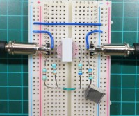
Vocal remover circuit, no chips, passives only

A tiny circuit that removes most of the lead vocal from a popsong (instant karaoke?). Audio examples demonstrate the working of the circuit. You need a small audio transformer, 4 resistors and a capacitor. The concept: Lead vocals are usually centered in the middle, so subtracting left from right removes these. Because bass signals are also mid but should not be removed, the circuit provides a bass bypass. More details can be found in the circuit description below.
Main application and advantage of the circuit is that it offers an instant "karaoke" converter between your mobile phone headphone output and some powered speakers line input. Once build, you could have this available as a very compact tool, no power supply is needed.
For other situations where you have enough preparation time and patience there are software processing tools that can process MP3 files and then remove vocals with a higher quality than this simple circuit.
Circuit description (see circuit file attached):
The transformer is used as a differential "amplifier" (gain=1) that subtracts the left channel from the right channel and presents the difference at the output. This way both the mid centered vocals and the bass signals are suppressed. The bass signals are recovered with a bypass RC lowpass filter (R1,R2,C1) that collects the bass from the input left+right and uses resistors (R3,R4) to add the bass signal again to the output signals.
Another trick creates a bypass for the very high frequencies above the voice spectrum (5kHz up). The transformer used is a small 1:1 audio transformer (see data zipfile provided, 1 Euro). These transformers usually have a few nanoFarad stray coupling between the windings, this model measured 3nF.
Here that stray capacitance is used to bypass some of high frequency contents (above voice) to the output, a highpass filter is formed by this 3nF stray capacitance in combination with the 6k8 resistors (R3,R4).
The 3nF value is not very critical, but if you use another transformer with less capacitance you could add some, and if it has more you could lower R3, R4.
None of the component values are really critical, I just picked them by listening, you can try to tweak them for what sounds better to you. For example: try changing the capacitor C1 value 0.47uF/1uF/2.2uF . A second order RC might improve things but I went for as simple as possible here.
Misc
I made up a handy adapter to connect 3.5mm connectors to a breadboard, pictures attached.


Discussie (2 opmerking(en))
RS-elc 1 jaar geleden
First: This circuit has very simple bass-bypass and high frequency-bypass filters so some voice leakage is induced there. If you filter too much though, you also loose a lot of the instrumental part of the sound, so I made it just good enough for a "sing-a-long" enabling amount of suppression.
Second: If you listen carefully to the sound examples you will notice that the remaining voice part sounds quite distant with a lot of reverb. As reverb is a stereo element in addition to the centre-placed direct voice this would mean that the voice-cancelling (based on a nulling principle) is doing a good job on the direct voice but it is intrinsically limited by some amount of added stereo reverb in the recording.
Considering your suggestion about the balance control, I do not think this would improve nulling here that much, a transformer is a very good differential "amplifier" (gain=1) by itself, common mode signals on the primairy winding do not induce a voltage at all in the secundary winding, only large unbalanced capacitive leakage could do so but here we already limited all capacitive coupling to a highpass filter mainly above the voice spectrum.
greetings,
Raymond
David Ashton 1 jaar geleden