

XR2206 Function Generator Kit
Assembling XR2206 IC based function generator kit
Introduction
Function generator is one of the most important instruments of an electronics laboratory. It is used for repairing and designing electronic circuits. It is used for testing electronic devices as well. Purchasing a new function generator from the market is not a big problem but not every electronics learner and hobbyist can purchase a new function generator like me due to their high costs. So for electronics learner's and hobbyist cheap function generators are available as DIY kits. XR2206 Function Generator kit is one of them. Although It is not as effective as a commercial one but it can be used to fulfil all the requirements of an electronics learner and hobbyist. Also the XR2206 function generator kit has very less features in comparison to a function generator that is used in electronics laboratories.
Features of XR2206 Function Generator Kit
- Low Cost (about 7$).
- Available in both pre soldered and solderable form.
- Small size and weight.
- Transparent case for for protecting the kit.
- Frequency Adjustable.
- Amplitude Adjustable.
- Cable of generating sine, square and triangle wave signals.
- Operates on 9V DC power supply.
- Instruction manual is included in the kit.
- All the components are THT(soldiering process is easy).
- Easy to operate.
List of Components (Included in the kit)
Resistors
Resistors
- R1------->1k
- R2------->50k
- R3------->5.1k
- R4------->330
- R5------->5.1k
- R6------->5.1k
- R7------->50k
- R8------->100k
Capacitors
- C1------->100uF
- C2------->0.1uF(104)
- C3------->10uF
- C4------->10uF
- C5------->1uF(105)
- C6------->0.047uF(473)
- C7------->0.002(222)
- C8------->100pF(101)
Integrated Circuit(IC)
- U1------->XR2006(DIP-16 package)
DC power jack
Male headers
Male headers
- J3------->2x5
- J2------->2x2
PCB Terminal(3 Pin)
Jumpers
PCB
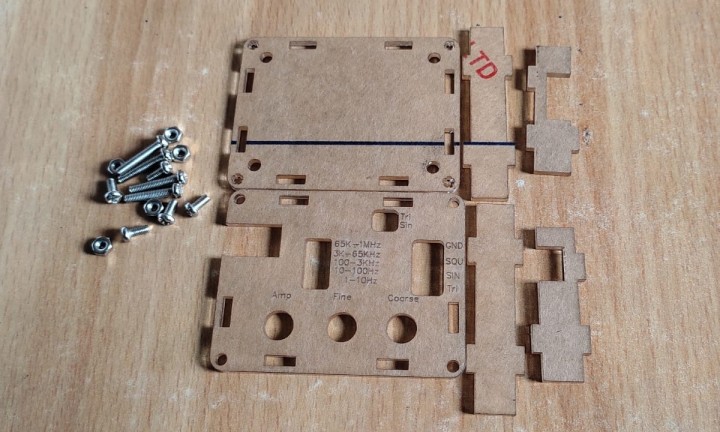
Transparent Acrylic Case
M3 Nut & Bolts
Potentiometer knob
Necessary Tools for Assembling the kit
For assembling this function generator kit following tools are compulsory.
Jumpers
PCB
Transparent Acrylic Case
M3 Nut & Bolts
Potentiometer knob
Necessary Tools for Assembling the kit
For assembling this function generator kit following tools are compulsory.
- Soldering Iron (60W)
- Soldering Wire (0.8mm)
- Soldering Flux
- Screw Driver
- Wire Cutter
- Acetone ( For cleaning the PCB after soldering)
- Brush
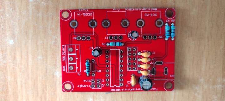
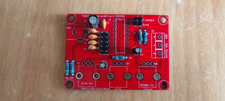
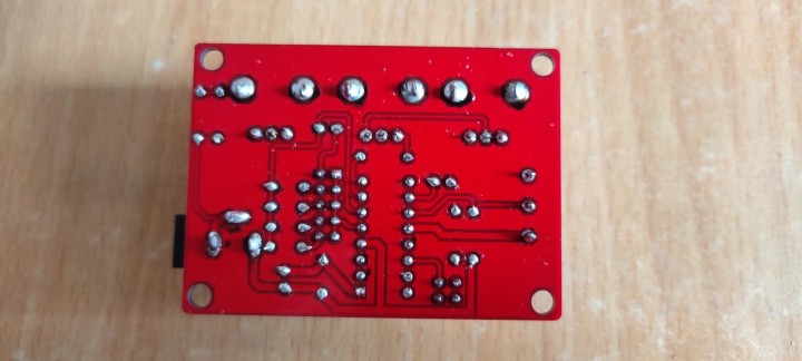
XR2206 kit PCB (Printed Circuit Board)


For Assembling the kit go through the following steps
Step-1: [Soldering Resistor]
This is the first step of whole soldering process. In this step we solder all the resistors included in the DIY kit on PCB. Before soldering the resistors we find their values. For finding the resistors values we can take the help of following resistors colour code chart:


Step-2: [Soldering Ceramic Capacitors]
In this step we have to solder all the ceramic capacitors. Like resistors ceramic capacitors do not have polarity also, so we can easily solder them on the PCB easily.

Step-3:[Soldering Electrolytic Capacitors]
In this step we solder the electrolytic capacitors. The Electrolytic capacitors have polarity so before mounting them on the PCB we need to find their positive and negative leads. Generally The longer lead of the electrolytic capacitor is +Ve and shorter lead is -Ve. After finding the polarity of electrolytic capacitors mount them on the PCB as shown below:
After mounting all three electrolytic capacitors bend their leads and make solder joints. After making the solder joints cut out their excess leads:
Step-4:[Soldering 2x5 & 2x2 Male headers]
In this step we solder 2x5 & 2x2 male headers. For this mount both of them on the PCB as shown in the given fig.
Step-5:[Soldering DC Jack]
In this step we solder the DC power jack. Mount the jack on the PCB as shown in the following Fig.

Now make solder joints. During soldering DJ jack please increase the temperature of soldering iron otherwise solder joint would not be clean.
Step-6:[Soldering IC holder]
In this step we solder the IC holder. Before mounting the IC holder on PCB please keep the cut mark (Notch) of IC holder at top side and flat side towards bottom side.
Step-7:[Soldering Potentiometers]
Before soldering the potentiometers we need to Identify their vales. The left and right potentiometers are of 50k and middle one is of 100k.

Step8:[Soldering PCB Terminal]
In this step we solder the 3-pin PCB terminal. This is the last component left for soldering. Mount the PCB terminal on the PCB as shown in the following fig.

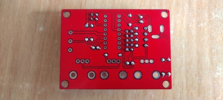
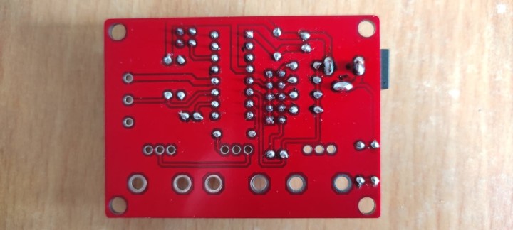
Step-9:[Cleaning the PCB with Acetone]
In this step we clean the PCB board with acetone and plastic brush. It is necessary because during soldering, soldering flux makes the PCB board dirty. After cleaning with acetone it looks as clean as new PCB.

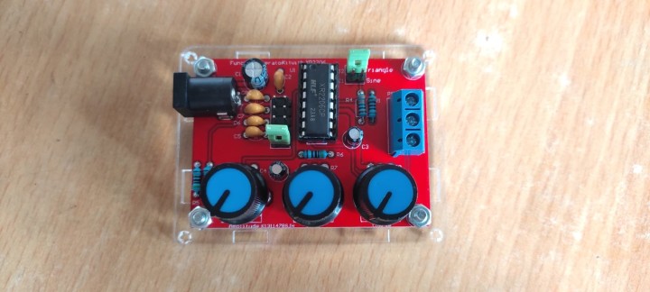
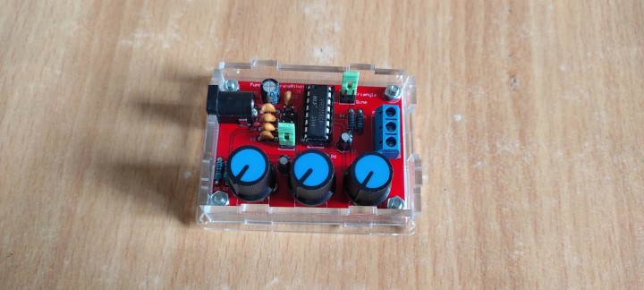
Step-10:[Preparing the Acrylic Case]
A transparent acrylic case is also provided in the kit to keep the PCB save. M3 nut & bolts is also included in the kit for fixing the PCB on the bottom acrylic sheet.
Remove the protecting layers of acrylic case insert M3 nuts as shown in the Fig.

Mount the Function generator PCB on the kit with the help of nuts & bolts. Use screw driver to tight the nuts.

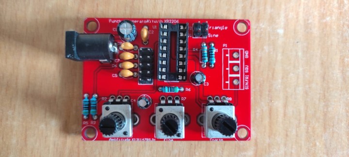
set the potentiometers to initial position and fix the potentiometers knobs as shown in the Fig.
also attach all four side layers as shown.
Now put the top acrylic sheet and tight it with screws and screw drivers.

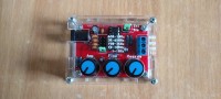
Now our KR2206 function generator kit is ready to use and it looks really nice.

Discussie (7 opmerking(en))
MTB55 8 maanden geleden
Deltor 9 maanden geleden
I was completely wrong - there was a guy sitting at a desk with a dirt cheap (< 15€) DSO138 China-scope plus some (broken) acrylic case with that already built XR2206 thingy.
He was talking in a strange obscure language - sometimes I thought there were fragments of English words perceptible - which I don't know or understand.
The most interesting thing in this video was a little insect or spider running over the desktop while he was turning some knobs to make changes onto the oscilloscope's display.
I think that guy should ask someone to speak some English comments to make clear what is that all about.
Gunther Jordan 9 maanden geleden
It was a part of my training to build this kit for checking and measuring signals and distortions etc. and I remember it being quite weak even in these days.
So now more then 50 years old I don't think this old chip will break any records today...
Deltor 9 maanden geleden
Elektor published (felt) 1000+ articles with the XR2206 in the 1970s and 1980s.
Just like the "Elektingel" - an electronic door bell.
My local dealer (Segor) and a renowned distributor (Digikey) both still list the XR2206.
But both have 0 (zero!) in stock - marked as obsolete!
You will have trouble to buy one anywhere (but at Elektor?).
Hans Grilnberger 9 maanden geleden
10% resistors are available as "4 band" components, the 4th ring is silver (10%) instead of gold (5%)
"5 band" resistors are available in 2% (5th / last ring is red) and 1% (last ring is brown). there is no last ring in silver available for "5 band" resistors.
The background: it wouldn't make sense to specify a 10% resistor with 4 digits if the 3rd digit is already overdetermined.
regarding "6 band" resistors: I do not know about any 4% resistor. Temp coefficients are specified for resistors better then 0,1% (which is 1000 ppm) only because temperature coefficients are in the 20 to 200 ppm range usually.
edringel@alum.mit.edu 9 maanden geleden
My greater concern comes from the video. Oscilloscope tracings show considerable distortion of both square waves and sine waves. A mod of this circuit that included the distortion reducing features of Figure 12 in the IC datasheet would have been interesting.
Deltor 9 maanden geleden
edringel@alum.mit.edu 9 maanden geleden
Deltor 9 maanden geleden
Sorry for writing in German - this was just because someone else already did so.
This (schematic download) was so not-obvious because after being heavily bored by scrolling down miles just to see some small pcb changes onto tons of photos, I didn't expect a download section (and overlooked it).
The author should put his prose including the photographs and colour code hints into a handy ready-to-print pdf document and make that part of the downloads - just for the totally unskilled.
The rest of this article should be shortened to approx. 10% of its current size just showing 3 photographs:
1. The schematic - not really a photo :-),
2. All parts of the kit,
3. The fully assembled kit.
I didn't watch the YouTube video because I don't expect anything interesting.
unikum 9 maanden geleden