

Measure input and output power
Discover Measure Power Quadrupole, a versatile measuring device for precise monitoring of input and output voltage, current, and power for DC converters. Optimize your energy systems with this powerful tool.
Measure Power Quadrupole
Measure input and output voltage, current and power for quadrupoles.

Highlights
- Accurate Measurements: Utilizing an INA168, it measures current on the high side with a range of 0 to 30A.
- Voltage Range: Capable of measuring voltages in the range of 0 to 60V.
- MPP Tracking: With PWM output, it enables Maximum Power Point (MPP) tracking for solar panels and more.
- Versatile Integration: The Measure4pole class allows you to use it as an object, facilitating MPP tracking and measuring.
How to Get Started
- Define your object with or without a connected OLED display.
- Set your calibration values and PWM settings.
- Track MPP and display values in real-time.
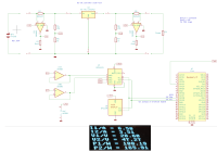
I use this measuring device to design and control step up or step down DC converters. It uses an INA168 to measure current in the high side line so that there can be a common ground for input and output. With the configuration R shunt = 10mOhm and Rout = 50kOhm for the INA168, there is a range 0…30A for the current.
The voltage range is 0…60V in the shown configuration.
The LM358 are selected for low offset voltage, it would be better to use special low offset op amps.
There is a PWM output that can be used to control the step-up converter. Using this, I could measure the MPP curve of my solar panels:

The module mpptrack_xx.py contains a class Measure4pole that allows to use the measuring device as an object. This allows MPP tracking and measuring:
m4p = Measure4pole(adc, pwmgen, oled = oled)
#m4p = Measure4pole(adc, pwmgen, oled = None)
m4p.set_pwm(0.3)
# Display values
i = 0
while True:
if i % 10 == 0:
if oled:
oled.print("MPP tracking")
m4p.mpp_track()
m4p.measure()
m4p.print_values()
m4p.print_oled()
i += 1
time.sleep(1)
Discussie (3 opmerking(en))
Jean-Claude Feltes 1 jaar geleden
There are breakout boards with the INA169 that has a transconuctance a bit different.
For my MPPT tracker I used these, soldering a 10mOhm shunt onto them, so I get a current range of 30A that fits me well.
Deltor 1 jaar geleden
You will get 9W of power dissipation at your shunt - a SMT type resistor will not withstand this.
When I searched for specs for your used shunt monitor INA168, I found that there are 4 very similar ICs from TI: INA138/139/168/169.
At first glance I couldn't tell the differences, because there weren't parameters listed at Digikey or Mouser at their parametric search.
The thing they don't tell is the transconductance:
the INA1*8 have 200µS (5kOhm at the inputs), while the INA1*9 have 1mS (1kOhm).
Their quiescent current also differs: 25µA and 60µA, respectively.
The other (but listed) parameter is their maximum input voltage:
the INA138 /139 can accept up to 36V and 40V, respectively, while the INA16* can deal with up to 60V.
In the data sheets all these parameters are, of course, listed!
Deltor 1 jaar geleden
You can use an arbitrary (common) value from an E-series, e.g. 47kOhm from E3, and do the adjustment in Soft-/Firmware.
Jean-Claude Feltes 1 jaar geleden
Content Director, Elektor 1 jaar geleden
Jean-Claude Feltes 1 jaar geleden
Look into the folder KiCAD.
There you have the original Schematic file.
This project is a sub product of my solar project found here:
https://github.com/jean-claudeF/SolarPower
There is a blog in PDF format (in German, I'm afraid) where you can see the evolution of the stepup supply for this project
and it uses the INA168 /169 to measure current on the high side, so that you can have a common ground between input and output. I have tried many things to get a good current measuring, and this seemed the best to me.