

eBUS Converter, Smarthome with RPi and Openhab
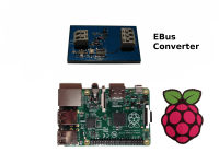
Build your own eBUS converter for a few bucks. Only 13 components are necessary.
The eBUS is a two-wire serial communication interface used in heating and solar energy appliances.
Some eBUS converters are very expensive, others are not. So I tried to build my own one.
The eBUS converter is bus powered. Voltage regulator is a LM1117-5.0V. On the right side of the schematic you have to set the voltage input level with the resistor R4. The output with the label RXD can directly connected to USB to Serial (TTL) adapter. The transmit part is currently not tested.
Orginal schematic is available from eBUS-wiki.
More information on Wikipedia.
Discussie (1 opmerking(en))
magicChristian 8 jaar geleden
Das Signal EBUS+ wird als Vcc benannt; das halte ich für ungünstg.
Das Signal EBUS- kommt am Schaltplan nicht vor (es ist mit GND identisch)
Der IC3 wird als LD1117AS33 bezeichnet - wäre die 3,3 Volt Version,
soll aber die 5 V Version sein LD1117#5:
Der Eingang an IC1 Pin 9 ist aber das wirkliche Problem:
Bei bestimmten EBUS+ Spannungen befindet sich das Gatter im linearen Bereich.
Das wird bei Vcc 5 V noch gut abgehen aber es ist ein größere Stromaufnahme zu erwarten
2 mögliche Abhilfen:
Entweder ein Gatter mit Schmitt Trigger Eingang zB. HEF40106.
Oder eine positive Rückkopplung und eine Hysterese einbauen: Anstelle des Poti einen fixen R von 15 k nach EBUS+ und eine 2 k Poti und einen R von 3,9 k nach GND. und von Pin 4 einen 56 k Widerstan an den Pin 9 ergibt eine Hysterese von etwas mehr als 1 V am EBUS+.